20
www.mega-motion.com Rascal
REAR COMPONENTS
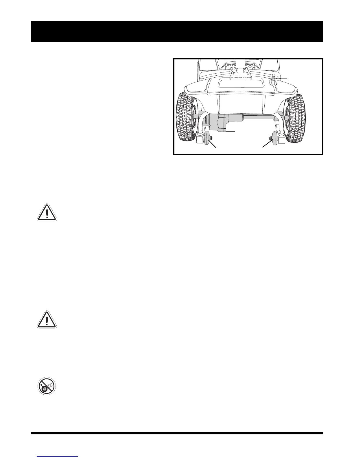
The manual freewheel lever, anti-tip wheels, and motor/transaxle assembly are located on your Travel
Scooter as shown. See figure 6.
WARNING! Before placing your Travel Scooter into or taking it out of freewheel mode,
remove the key from the key switch. Never sit on a Travel Scooter when it is in freewheel
mode. Never put a Travel Scooter in freewheel mode on any incline.
Manual Freewheel Lever
Whenever you need or want to push your Travel Scooter for short distances, you can put it in
freewheel mode.
1. Locate the manual freewheel lever at the top right of the rear section.
2. Push forward on the manual freewheel lever to disable the drive system and the brake system. You may
now push your Travel Scooter.
3. Push the manual freewheel lever rearward to reengage the drive and the brake systems; this takes your
Travel Scooter out of freewheel mode.
WARNING! When your Travel Scooter is in freewheel mode, the braking system is
disengaged.
Disengage the drive motors only on a level surface.
Ensure the key is removed from the key switch.
Stand to the side of the Travel Scooter to engage or disengage freewheel mode. Never
sit on a Travel Scooter to do this.
After you have finished pushing your Travel Scooter, always return it to the drive mode
to lock the brakes.
Anti-Tip Wheels
The anti-tip wheels are an integral and important safety feature of your Travel Scooter. They are bolted to
the frame at the rear of the Travel Scooter.
PROHIBITED! Do not remove the anti-tip wheels or modify your Travel Scooter in any way
that is not authorized by Mega Motion.
Motor/Transaxle Assembly
The motor/transaxle assembly is an electromechanical unit that converts electrical energy from your
Travel Scooter’s batteries into the controlled mechanical energy that drives the Travel Scooter’s wheels.
III. YOUR TRAVEL SCOOTER
Speed Adjustment Dial
This dial allows you to preselect and limit your
Travel Scooter’s top speed.
The image of the tortoise represents the
slowest speed setting.
The image of the hare represents the fastest
speed setting.
Battery Condition Meter
When the key is fully inserted into the key
switch, this meter indicates approximate bat-
tery strength. For further information on the
battery condition meter, see IV. “Batteries
and Charging.”
MANUAL
FREEWHEEL
LEVER
ANTI-TIP WHEELS
Figure 6. Rear Components
MOTOR/
TRANSAXLE
ASSEMBLY
 Loading...