EasyManuals Logo
Home>Mercury Security>Recording Equipment>MR51e

Mercury Security MR51e User Manual

Mercury Security MR51e
9 pages
To Next Page IconTo Next Page
To Previous Page IconTo Previous Page
Page #2 background imageLoading...
Page #2 background image
Mercury Security © 2015 MR51e DOC 10107-0035 REV 1.06 Page 2
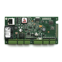
MR51e Terminal Blocks and Jumpers/Jacks:
MR-51E CONNECTIONS
TB1-1
IN1
Input 1
TB1-2
IN1
TB1-3
IN2
Input 2
TB1-4
IN2
TB2-1
IN3
Input 3
TB2-2
IN3
TB2-3
IN4
Input 4
TB2-4
IN4
TB3-1
VO
Reader 1 Power Output 12 VDC
TB3-2
LED
Reader 1 LED Output
TB3-3
BZR
Reader 1 Buzzer Output
TB3-4
CLK
Reader 1 CLK/Data 1/TR+
TB3-5
DAT
Reader 1 DAT/Data 0/TR-
TB3-6
GND
Reader 1 Ground
TB4-1
LED
Reader 2 LED Output
TB4-2
BZR
Reader 2 Buzzer Output
TB4-3
CLK
Reader 2 CLK/Data 1 Input
TB4-4
DAT
Reader 2 DAT/Data 0 Input
TB5-1
VO
Auxiliary Power Output 12 Vdc
TB5-2
GND
Auxiliary Power Output Ground
VIN
Input Power 12 Vdc (from local power supply)
TB5-4
GND
Input Power Ground
TB6-1
NO
Relay K1 Normally Open Contact
TB6-2
1-C
Relay K1 Common Contact
TB6-3
NC
Relay K1 Normally Closed Contact
TB6-4
NO
Relay K2 Normally Open Contact
TB6-5
2-C
Relay K2 Common Contact
TB6-6
NC
Relay K2 Normally Closed Contact
Jumpers:
JUMPER
SET AT
DESCRIPTION
J1
N/A
Factory Use Only
J2
N/A
Factory Use Only
J3
N/A
Factory Use Only
J4
N/A
Factory Use Only
J5
PoE
MR-51E powered from the Ethernet connection
12V
MR-51E powered from an external 12 Vdc power
source connected to TB5-3 (VIN), TB5-4 (GND)
J6
N/A
Ethernet Connection with POE support
J7
N/A
Factory Use Only

Questions and Answers:

Question and Answer IconNeed help?

Do you have a question about the Mercury Security MR51e and is the answer not in the manual?

Mercury Security MR51e Specifications

General IconGeneral
BrandMercury Security
ModelMR51e
CategoryRecording Equipment
LanguageEnglish