Mercury Security © 2015 MR51e DOC 10107-0035 REV 1.06 Page 3
3. DIP Switches:
The addressing mode used is determined by the DIP switch setting on the MR51e:
MSC-Specific DHCP (original method)
Programming Mode for Static IP Address Assignment
MSC-Specific DHCP (original method)
Notes:
Public DHCP and Static IP Addressing Modes are available with MR51e firmware
revisions 1_4_2 and later
All other DIP switch settings are reserved for future use
Press S2 to reset board after DIP switch is changed for new address mode
4. Input Power:
The MR51e is powered by one of two ways (jumper selected, J5):
Power is supplied via the Ethernet connection using PoE, fully compliant to IEEE 802.3af
Or local 12 Vdc power supply, TB5-3 (VIN), TB5-4 (GND).
5. Communication Wiring:
Communication between the EP controller and the MR51e is Ethernet (10Base T/100Base-TX).
It is not recommended to connect the MR51e to a public intranet.
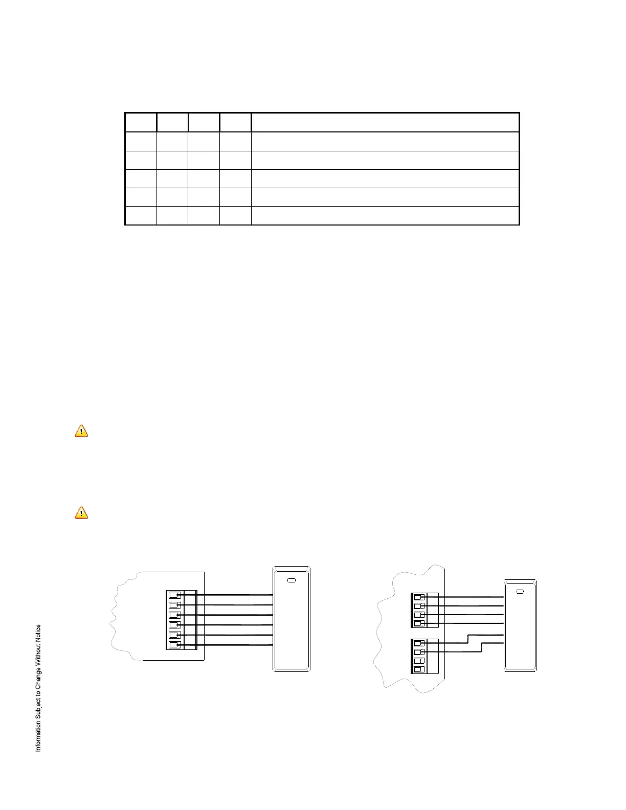
6. Reader Wiring:
Reader port 1 supports TTL (D1/D0, Clock/Data), F/2F, or 2-wire RS-485 device signaling. Reader port
2 supports TTL (D1/D0, Clock/Data), or F/2F signaling. Power to reader port 1 is 12 Vdc at 180 mA
maximum. Reader port 2 may be powered from the auxiliary power supply output; TB5-1 and TB5-2.
Readers that require different voltage or have high current requirements must be powered separately.
Refer to the reader manufacture specifications for cabling requirements. In the 2-wire LED mode, the
buzzer output is used to drive the second LED. Reader port configuration is set via the host software.
When powering any remote device(s) by the MR51e, care must be taken not to exceed the maximum
current available. Cable gauge must also be evaluated. See specifications section for details.
Reader Port 1
Typical D1/D0 or Clock/Data Reader
Reader Port 2
Typical D1/D0 or Clock/Data Reader
1
TB3
VO (12 Vdc)
GND
LED
BZR
CLK/D1
DAT/D0
FIRST READER PORT
TB4
1
BZR
DAT/D0
CLK/D1
LED
SECOND READER PORT
1
TB5
GND
VIN
GND
VO
(12 Vdc)
 Loading...