Mercury Security © 2018 LP2500 DOC 10107-0063 REV 1.02 Page 3
Bulk Erase Steps: Do not remove power during steps 1-8.
1. Set S1 DIP switches to: 1 & 2 "ON", 3 & 4 "OFF".
2. Apply power to the LP2500 board. LED 1 on for about 15 seconds while LP2500 boots up.
3. After the LP2500 boots up, watch for LEDs 1 & 2 and 3 & 4 to alternately flash at a 0.5 second rate.
4. Within 10 seconds after the above pattern starts, change switches 1 or 2 to "OFF". If these switches are
not changed, the LP2500 board will power up using the OEM default communication parameters.
5. LED 2 will flash indicating that the configuration memory is being erased.
6. Full memory erase takes up to 60 seconds, usually a lot less.
7. When complete, only LEDs 1 & 4 will flash for about 3 seconds.
8. The LP2500 board will complete its initialization in 2 seconds after LEDs 1 & 4 stop flashing.
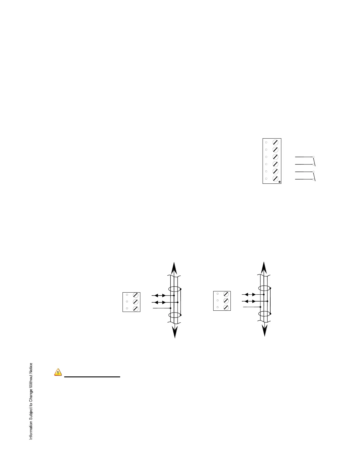
5. Input Power, Cabinet Tamper and UPS Fault Input Wiring:
The LP2500 requires 12 to 24 Vdc power. Locate power source as close to
the unit as possible. Connect power with minimum of 18 AWG wire.
Connect
the GND signal to earth ground in ONE LOCATION within the system!
Multiple earth ground connections may cause ground loop problems
and is not advised.
Observe POLARITY on 12 to 24 Vdc input!
There are two dedicated inputs for cabinet tamper and UPS fault monitoring.
Normal (safe) condition is a closed contact. If these inputs are not used,
suggest installing a jumper wire.
6. Communication Wiring:
The LP2500 controller communicates to the host via: on-board Ethernet 10-BaseT/100Base-TX port and/or the
USB port (2.0) with an optional Micro USB to Ethernet adapter.
Ports 1 and 2 utilize 2-wire RS-485 interface. The interface allows multi-drop communication on a single bus
of up to 4,000 feet (1,219 m). Use 1-twisted pair, shielded, 120 ohm impedance, 24 AWG. 4,000 ft. (1,219 m)
maximum cable length.
IMPORTANT NOTE! Install the termination jumper ONLY on the panel at each end of the RS-485 bus.
Failure to do so will compromise the proper operation of the communication channel!
7. Memory and Real Time Clock Backup Battery:
The static RAM and the real time clock are backed up by a lithium battery when input power is removed. This
battery should be replaced annually. If data in the static RAM is determined to be corrupt after power up, all
data, including flash memory, is considered invalid and is erased. All configuration data must be re-
downloaded. Remove the insulator from the battery holder after installation. Battery type: BR2330 or CR2330.
 Loading...