ENGLISHen
12
This also applies to dust from other materials such
as some timber types (like oak or beech dust),
metals, asbestos. Other known diseases are e.g.
allergic reactions, respiratory diseases. Do not let
dust enter the body.
Observe the relevant guidelines and national
regulations for your material, staff, application and
place of application (e.g. occupational health and
safety regulations, disposal).
Collect the particles generated at the source, avoid
deposits in the surrounding area.
Use suitable accessories for special work. In this
way, fewer particles enter the environment in an
uncontrolled manner.
Use a suitable extraction unit.
Reduce dust exposure with the following measures:
- do not direct the escaping particles and the
exhaust air stream towards yourself or nearby
persons or towards dust deposits,
- use an extraction unit and/or air purifiers,
- ensure good ventilation of the workplace and keep
it clean using a vacuum cleaner. Sweeping or
blowing stirs up dust.
- Vacuum or wash protective clothing. Do not blow,
beat or brush protective gear.
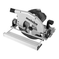
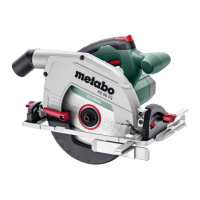
See page 2.
1 Connector (extraction connection piece / chip
ejection)
2Handle
3Trigger
4 Locking button
5 Side handle
6 Undercut limit stop (increases the max.
diagonal cut angle from 45° to 47°)
7 Scale (diagonal cut angle)
8 Locking screw (parallel guide)
9 2 Locking screws (diagonal cuts)
10 Marking (saw blade outer diameter)
11 Cutting indicator
12 Parallel stop
13 Marking (for reading off the scale on the parallel
guide)
14 Guide grooves to place the machines on guide
tracks from different manufacturers
15 Adjusting screw (adjust saw disc angle)
16 Guide plate
17 Hexagon wrench
18 Storage for hexagon wrench
19 Locking screw (depth of cut)
20 Scale (depth of cut)
21 Saw blade fixing screw
22 Outer saw blade flange
23 Saw blade
24 Lever (for swivelling back the movable guard)
25 Inner saw blade flange
26 Movable safety guard
27 Spindle locking button
Before commissioning, check that the rated
mains voltage and mains frequency stated on
the type plate match your power supply.
Always install an RCD with a maximum trip
current of 30 mA upstream.
Pull the plug out of the plug socket before any
adjustments or servicing are performed.
6.1 Setting cutting depth
Loosen the locking screw (19). Raise or lower the
motor section against the guide plate (16). Read the
depth of cut that has been set from the scale (20).
Tighten the locking screw (19) again.
It is advisable to set the depth of cut in such a way
that no more than half of each tooth on the saw
blade juts out under the workpiece. See illustration
on page 2.
Note: The clamping power of the locking screw (19)
can be adjusted. Unscrew the screw on the lever to
do this. Remove lever and mount offset
anticlockwise. Secure with screw. Ensure that
cutting depth adjustment moves freely when the
lever is open.
6.2 Slanting saw blade for diagonal cuts
Loosen the locking screws (9). Tilt the motor section
against the guide plate (16). Read the angle which
has been set from the scale (7). Tighten the locking
screws (9) again.
For a diagonal cut angle of 47°, push down the
undercut limit stop (6).
6.3 Correcting the saw disc angle
If, at 0°, the saw blade is not at right angles to the
guide plate: use the adjustment screw (15) to
correct the saw blade angle.
6.4 Setting extraction nozzle / chip ejection
The nozzle (1) can be rotated to the desired position
to extract or eject chips. To do this, push the nozzle
in up to the stop, turn and pull out again. The nozzle
can be locked in 45° increments so that it cannot
turn.
Sawdust extraction
To extract the sawdust, connect a suitable
extraction unit with suction hose to the machine.
7.1 Switching on and off
Switching on: Push the locking button (4) forwards
and hold, then actuate the trigger (3).
Switching off: Release the trigger switch (3).
7.2 Working Directions
Lay out the mains cable such that the cut can be
executed without obstruction.
The marking (10) on the upper guide plate assists
you in positioning the saw on the workpiece and
5. Overview
6. Initial Operation, Setting
7. Use
 Loading...