4
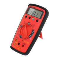
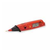
Measuring DC Voltage See Figure -1-
1. Set the Function Switch to
v
.
2. If RANGE is displayed, press the RANGE button to enable autoranging.
3. Connect the Test Leads: Red to
E
, Black to COM
4. Connect the Test Probes to the circuit test points.
5. Read the display, and, if necessary, correct any overload (
o
) conditions.
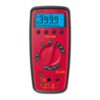
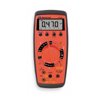
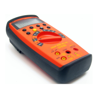
Measuring AC + DC Voltage (True rms)See Figure -2- & -3-
See Additional Features to find out the advantages of true rms.
1. Set the Function Switch to
v
.
2. If DC is displayed, press the yellow button to turn on AC+DC.
3. If RANGE is displayed, press the RANGE button to enable autoranging.
4. Connect the Test Leads: Red to
E
, Black to COM
5. Connect the Test Probes to the circuit test points.
6. Read the display, and, if necessary, correct any overload (
o
) conditions.
Measuring AC Voltage (True rms) See Figure -2- & -3-
See Additional Features to find out the advantages of true rms.
1. Set the Function Switch to
V
.
2. If dBm is displayed, press the yellow button to turn on AC.
3. If RANGE is displayed, press the RANGE button to enable autoranging.
4. Connect the Test Leads: Red to
E
, Black to COM
5. Connect the Test Probes to the circuit test points.
6. Read the display, and, if necessary, correct any overload (
o
) conditions.
Preparing for Current Measurements
• Turn off circuit power before connecting the Test Probes.
• Allow the meter to cool between measurements, if current measurements
approach or exceeds 10 amps.
• A warning tone sounds if you connect a test lead to a current input while a
current function is not selected.
• Open circuit voltage at the measurement point must not exceed 1000 V.
• Always measure current in series with the load. Never measure current across a
voltage source.
 Loading...