8.2 Pilot valve
Remove the pilot valve (44) by first loosening the nuts (49) and then
by lifting off the protective plate (48), the changeover piece (46)
and the gasket (45).
The pilot valve spool (44.2) should slip easily in the pilot valve
body (44.1).
If the pilot valve sticks, wash the body and spool with solvent.
NOTE:
The pilot valve body and spool constitute a pair, and must not
be replaced separately.
See the exploded view for the correct installation position of the
pilot valve. The size code for the pilot valve on the body, for example
DIA 4.0, must be visible on the right side.
Check the condition of the O-rings (43, 47) and of the gasket (45). The
end of the leaf spring on the beam must be on top of the pilot valve spool,
Figure 11. Make sure that the end of the beam (5) goes into the spool
groove without sideways deflections. After tightening the nuts (49), check
the beam once again by hand to see that the pilot valve moves readily.
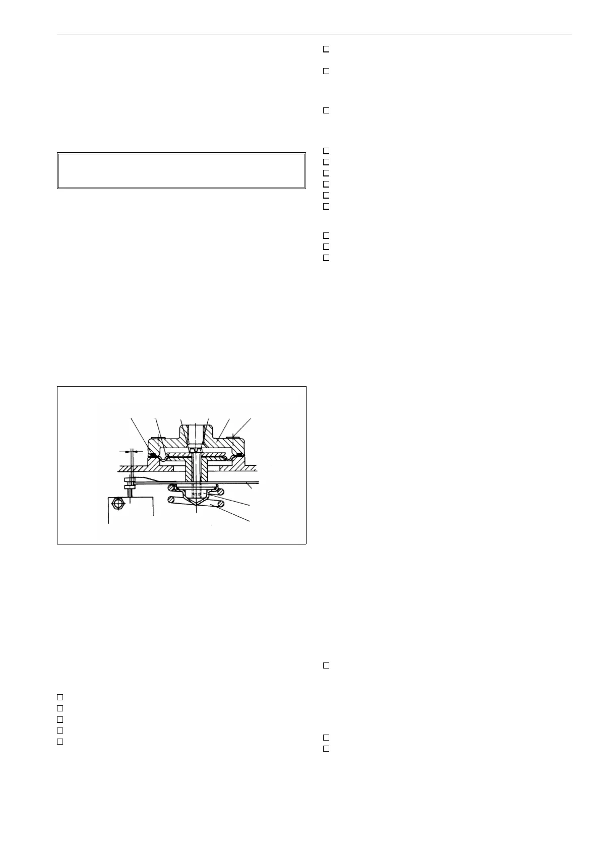
8.3 Replacement of the diaphragm
Remove the feedback spring (60), loosen the screws (23) and
remove the screw (15). Replace the diaphragm (14).
Note the correct installation position for the diaphragm, with the
convolution downward. See Figure 14.
Check the condition of the washer (55) when assembling and secure
the upper spring plate (16) with e.g. Loctite. Check that the O-ring
(11) is in place. Tighten the cover screws (23) evenly. The positioner
adjustment should be checked after replacement of diaphragm.
Note. O-ring (11) in the old construction only (manufactured
before 12/94).
9 TROUBLE SHOOTING
1. Signal pressure change does not affect actuator position
supply pressure too low
signal pressure tubes leak
diaphragm damaged
pilot valve sticks
changeover piece seals leak
tube installations between positioner and actuator,
changeover piece or cam position wrong, see Fig. 4
actuator or valve jammed
2. The actuator reaches final position with a small signal pressure
change
the tube installation between positioner and actuator, the
changeover piece or the cam position wrong.
3. Inaccurate positioning
pilot valve dirty
beam (5) pushes pilot valve spool sideways
diaphragm damaged
actuator torque too low
supply pressure too low
valve torque requirement increased
4. Overshooting or too slow positioning
pilot valve dirty or wrong size, see Table 2
supply air tube too small or supply air filter dirty
valve sticks
10 OPTIONS
10.1 NP700/B and NP700/B1
Equipped with a flameproof enclosure I/P converter.
To be adjusted like for standard posioners. Do not make any
adjustments for the I/P converter!
10.2 NP700/GN natural gas construction
For clean "sweet" natural gas instead of compressed air. Like standard
construction but with 3/4 NPT exhaust port.
Please note: do not remove the exhaust port (4).
10.3 NP700/R dust-proof construction (IP 65)
For extremely dusty environments. The protective cover (3) behind
the standard posioner is replaced with an exhaust port. The port
has a 3/4 NPT filter.
Please note: do not remove the exhaust port (3).
10.4 NP700/A with pressure gauges
A standard positioner can be equipped with a pressure gauge block.
The block (70) is attached with tree sef-tapping screws (72). The
O-rings (71, 3 pcs.) must be in position before mounting. Check
tightness after mounting.
For all other constructions see Type Code, Chapter 14.
11 TOOLS
In addition to standard general tools, you need the following
equipment:
calibration device for adjustments
12 ORDERING SPARE PARTS
When ordering spare parts, always include the following informa-
tion:
Type code (from ID plate)
ID code of the spare part (from spare part leaflet),
description and quantity
NOTE:
gap required
5
55
11
14
15
22
23
16
60
Fig. 14. Replacement of diaphragms
11
 Loading...