2.6 Instrument air supply
CAUTION:
Do not exceed the permitted actuator supply air
pressure!
The supply air must be clean, dry and oil-free instrument air, e.g.
according to standard ISA S7.3-81. Supply pressure is 0.14-1.0 MPa
/ 1.4-10 bar (20-140 psi).
3 INPUT SIGNAL AND DIRECTIONS
OF OPERATION
Figure 4 assists in choosing the right segment for the cam plate (29)
and position for the changeover piece (46).
3.1 Changeover piece
The function of connection C1 and C2 can be altered by turning
the changeover piece (46). The diagram D (or R) shown on the
protective plate (48) functions when the symbol D (or R) is
visible in the lower lefthand corner of the changeover piece (46).
D = direct, R = reverse.
External changes in the tubes are not needed. Positioner NP727 is
an exception (DIA6HC pilot valve). Then the changeover piece
must always be in position R and the external tubes mounted in
accordance with Fig. 7.
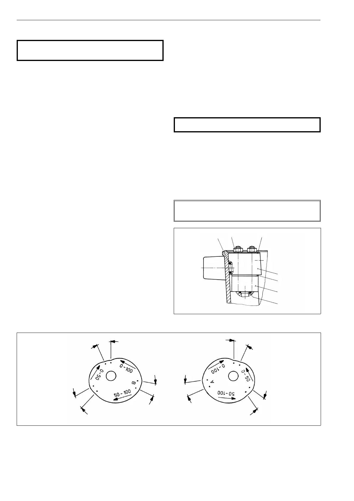
3.2 Cam plate
The figures marked on the cam plate (29) are the signal ranges
expressed as percentages, for example 0-100 corresponds to 20-100
kPa (3-15 psi), or 50-100 to 60-100 kPa (9-15 psi), see Fig. 8.
The arrows on the cam show the direction it must turn when the
input signal is rising in the cam segment in question.
The non-rising segments between the rising segments are
roughly 15-20º.
4 PRELIMINARY ACTIONS FOR THE
ADJUSTMENT
Set the valve’s open and closed limits with the actuator limiter screws; see
the valve instruction manual. The changeover piece (46) and the cam (29)
must be in correct positions. Check the pilot valve size from Table 2.
The adjustment must always be carried out when the supply
pressure has been changed.
Please note that operating of the valve is required during the
adjustment.
4.1 Position of the changeover piece
CAUTION:
Do not dismantle a pressurized positioner!
Choose the position of the changeover piece, D or R, from Fig. 7
in accordance with the function desired.
Turn the changeover piece (46) when necessary.
Loosen the nuts (49) and remove the protective plate (48). Pull out
the changeover piece (46). Check the O-rings (47, 2 pcs.) and apply
silicone grease lightly if needed. Place the changeover piece (46) and
the protective plate (48) in the case. Tighten the nuts (49) evenly,
one after the other.
NOTE:
Check that the changeover piece is mounted correctly: Sym-
bol D or R is visible in the lower left hand corner.
60-100 kPa (9-15 psi)
rising signal opens
60-100 kPa (9-15 psi)
rising signal closes
20-100 kPa (3-15 psi)
rising signal closes
20-100 kPa (3-15 psi)
rising signal opens
20-60 kPa (3-9 psi)
rising signal closes
20-60 kPa (3-9 psi)
rising signal
opens
segment C
segment C
segment E
segment D
segment E
~ 15°
~ 15°
~ 15°
~ 15°
~ 15°
~ 15°
Fig. 8. Input signal ranges
48
47
49
43
44
45
46
Fig. 9. Mounting the changeover piece
8
 Loading...