SECTION 3 - M. FRAME, ADJ. RING, TRAMP REL. & CLRNG JACK ASSY
MP SERIES CONE CRUSHER TECHNICAL REFERENCE MANUAL
3-25
20. Reinstall all hose connections to the
cylinder, bleed the air from the tramp release
circuit and pressurize the system and check
for leaks. Refer to Bleeding the Tramp
Release Circuit in Section 12 for
instructions on bleeding and pressure testing
the tramp release circuit.
3.4.9 Accumulator Bladder Replacement
For accumulator bladder replacement procedure,
refer to Accumulator Repair in Section 12.
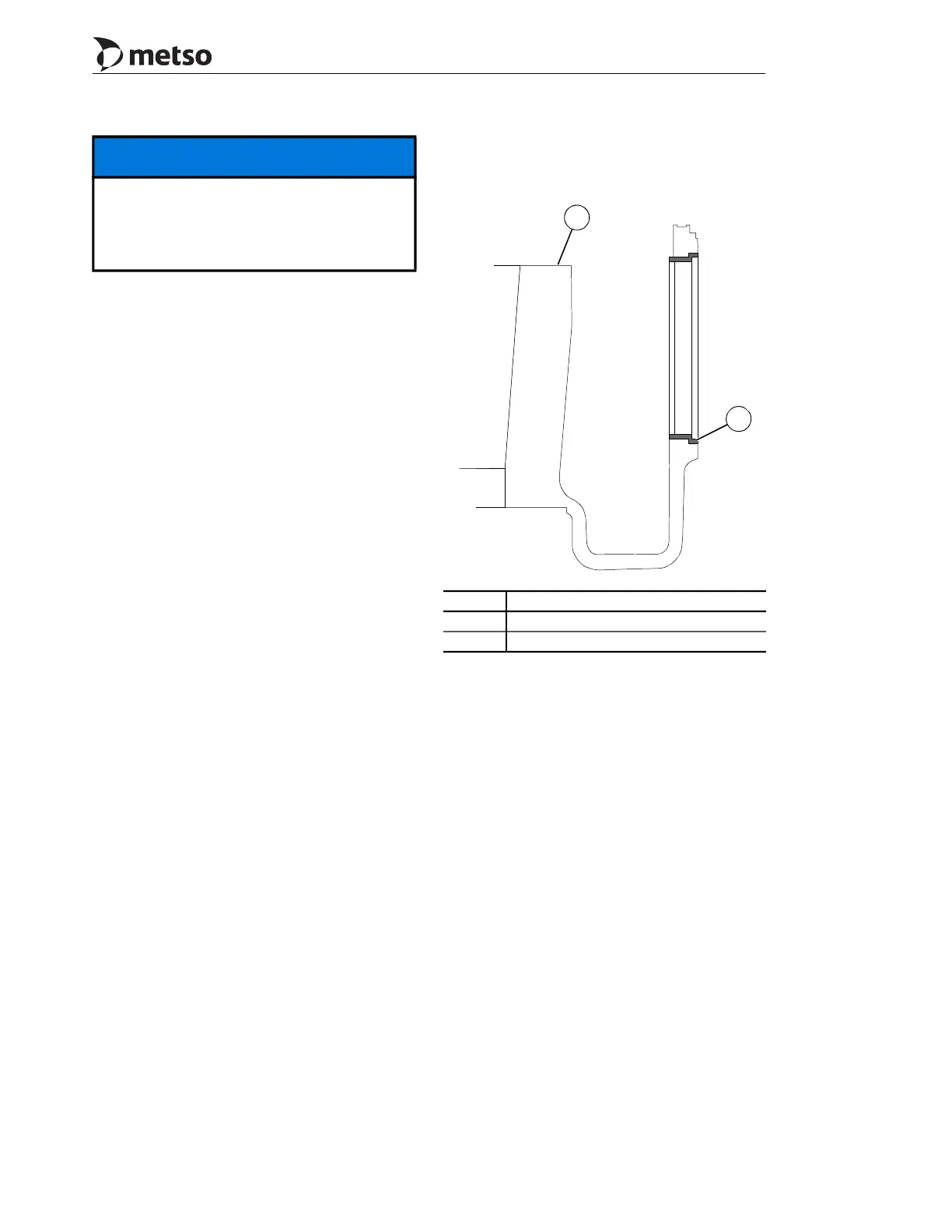
3.4.10 Main Frame Ring Replacement
A frame ring has been installed into the main frame
at the inner countershaft box as shown in
Figure 3-18. The purpose of this ring is to eliminate
the need of having to remove the frame from the
foundation to rework the inner bore (due to
excessive bore wear). If excessive bore wear
occurs, all that need be done is to replace the frame
ring. To replace the frame ring proceed as follows:
1. Remove the following components to gain
access to the ring:
– Bowl (Section 8)
– Head (Section 7)
– Socket and Socket Liner (Section 6)
– Eccentric (Section 5)
– Countershaft Box (Section 4)
2. Drive the ring out of the frame bore from
inside the pinion well toward the outside.
3. Clean frame bore, inspect and measure
diameters. Convey this information to Metso
Product Support Department for possible
rework requirements.
4. Clean the new frame ring O.D. with Loctite
Safety Solvent 75559, alcohol or acetone.
5. Cool ring to at least the temperature
difference between ring and frame defined
in Figure 3-19.
6. Install ring into frame. Allow temperatures
of the Ring and Frame to normalize before
installing countershaft box into frame.
Figure 3-18 Main Frame Ring
3.4.11 Adjustment Ring Installation
The adjustment ring assembly consisting of the dust
shell, pin bushing, pin covers, clamping ring and
clamping cylinders has been shipped assembled as
one unit (refer to Figure 3-20).
To assemble the adjustment ring assembly onto the
main frame do the following:
1. Attach shackles and lifting slings to the lift
lugs, four on the MP1000, three on the
MP800, located on the outside diameter of
the adjustment ring. Refer to Figure 3-7 and
Figure 3-20.
2. Coat the Adjustment Ring seat with a
lithium base grease, NLGI No.1 containing a
minimum of 3% molybdenum disulfide.
NOTICE
Do not pump oil into the tramp release
circuit before the accumulators are
pre-charged with nitrogen. This could
damage the bladder and necessitate an
accumulator replacement.
Callout Description
1 Main frame
2 Main frame ring
1
2
 Loading...