SECTION 3 - M. FRAME, ADJ. RING, TRAMP REL. & CLRNG JACK ASSY
3-28
MP SERIES CONE CRUSHER TECHNICAL REFERENCE MANUAL
3.4.12 Adjustment Ring Disassembly
The various sealing and clamping components that
are associated with the adjustment ring can be
detached and removed from the adjustment ring
while the adjustment ring is left in place on the
main frame. Main frame seat liner or fulcrum bar
replacement will, however, require that the
adjustment ring be removed from the main frame.
To detach and remove the adjustment ring
components, proceed as follows:
1. Remove the bowl assembly as instructed in
Section 8.
2. If the clamping ring is to be removed from
the adjustment ring, then first remove the
dust shell from the adjustment ring by
removing the series of capscrews and
lockwashers installed around its lower
flange and then lift the shell off the ring.
If the clamping ring is not to be removed
from the adjustment ring, then proceed to
step 6.
3. Remove the hex head bolts and spacers that
are used to hold the clamp ring when the
bowl assembly is rotated. There are eight
bolts and spacers on the MP1000 and six on
the MP800. Refer to Figure 3-23.
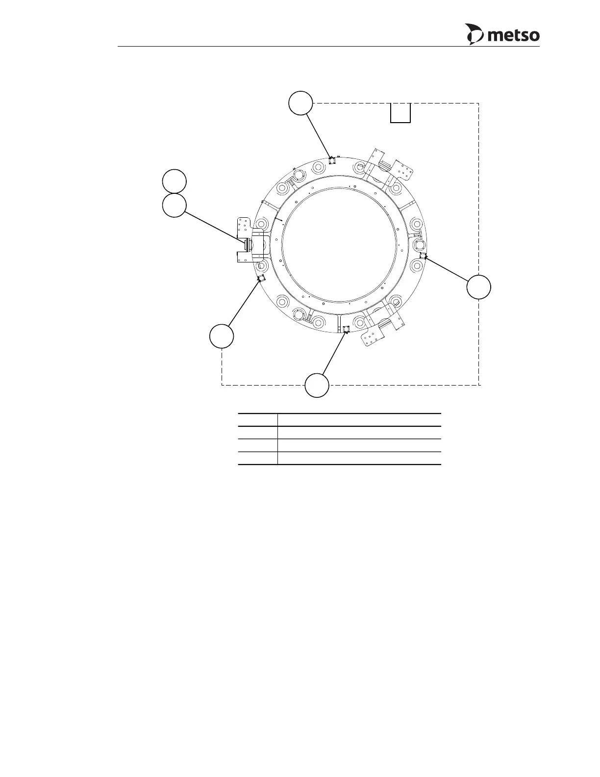
Figure 3-22 Vibration Sensor Locations (MP800 Shown)
VT
VE
n0540
VE
VE
VE
ZS
ZS
Callout Description
VE Vibration Sensor
VT Vibration Transmitter
ZS Proximity Sensor
 Loading...