7 NP 72 en 9
Loosen the screw (57), remove the indicator (32), loosen the
screw (31) and the locking wheel (30). Turn the cam plate
(46) to the desired side.
In case of α
0
adjustment proceed acc. to Sections 6.1 and
6.2.
Place the roller so that its contact point is 1 mm (0.04") from
the beginning of the rising segment. Then tighten the lock-
ing wheel (30) and the screw (31).
5 BASIC ADJUSTMENT
Basic adjustment is made to rotary and butterfly valves.
Please note the procedures in Chapter 4 before the adjust-
ment.
1. Switch on the supply pressure (S) and the input signal
(IN).
2. Set the input signal at the closed limit of the valve so
that it is 2 % i.e. 0.02 bar (0.2 psi) higher or lower than
the limit value, e.g. 0.2 + 0.02 = 0.22 bar (3 + 0.2 = 3.2 psi)
or 1.0 - 0.02 = 0.98 bar (15 - 0.2 = 14.8 psi). Loosen the
screw (56). Turn the zero adjustment screw (67) so that
the actuator comes slowly to the closed limit. Tighten
the screw (56) always after the zero adjustment. The
valve should open slightly with a 4 % change in signal,
that is 0.03 bar (0.5 psi), e.g. 0.2 + 0.03 = 0.23 bar (3 + 0.5
= 3.5 psi) or 1.0 - 0.03 = 0.97 bar (15 - 0.5 = 14.5 psi). See
Figures 8 and 9.
3. Set the input signal to the other limit value. The valve
should be entirely open at 100 %, i.e. 1.0 bar (15 psi) or
0.2 bar (3 psi). The valve should start to operate to
closed direction at 98 %, i.e. 0.98 bar (14.0 psi) or 0.22
bar (3.2 psi). The range, i.e. turning angle, changes when
the effective lenght of the spring (60) is increased or
decreased by turning the range adjustment nut (60.3).
See Fig. 9.
4. The zero and range adjustments affect each other, so
stages 2 and 3 must be repeated a few times.
5. Screw on the pointer (32) into place so that the yellow
line is in the direction of the valve closing member.
Tighten the screw (57).
6 α
0
ADJUSTMENT
α
0
adjustment is made to segment and ball valves. This
adjustment takes into account the "dead angle" α
0
of the
ball valve. The entire signal range is then used for effective
The same adjustment method can be applied to butterfly
valves in papermills for pulp flow control to avoid the dewa-
tering of the pulp near the closed position of the disc.
Table 3 shows the shift on the circumference of the cam
equal to the "dead angle" of the valve, Figure 11, in various
cam segments (C, E, D).
Please note the procedures in Chapter 4 before the adjust-
ment.
1. Mark the shift in question on the edge of the cam, Fig. 11
and Table 3. Dimensions do not have to be measured if
the dead angle can be reliably noticed from position of
the closing member.
2. Lock the cam so that the roller touches the edge of the
Fig. 8 Basic and
α
0
adjustments
POSITION %
Rising input signal closes valve
Rising input signal opens valve
max 2 %
INPUT SIGNAL %
safety range 2 %
Basic adjustment α
0
adjustment
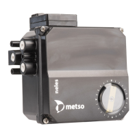
Fig. 9 Zero and range adjustments
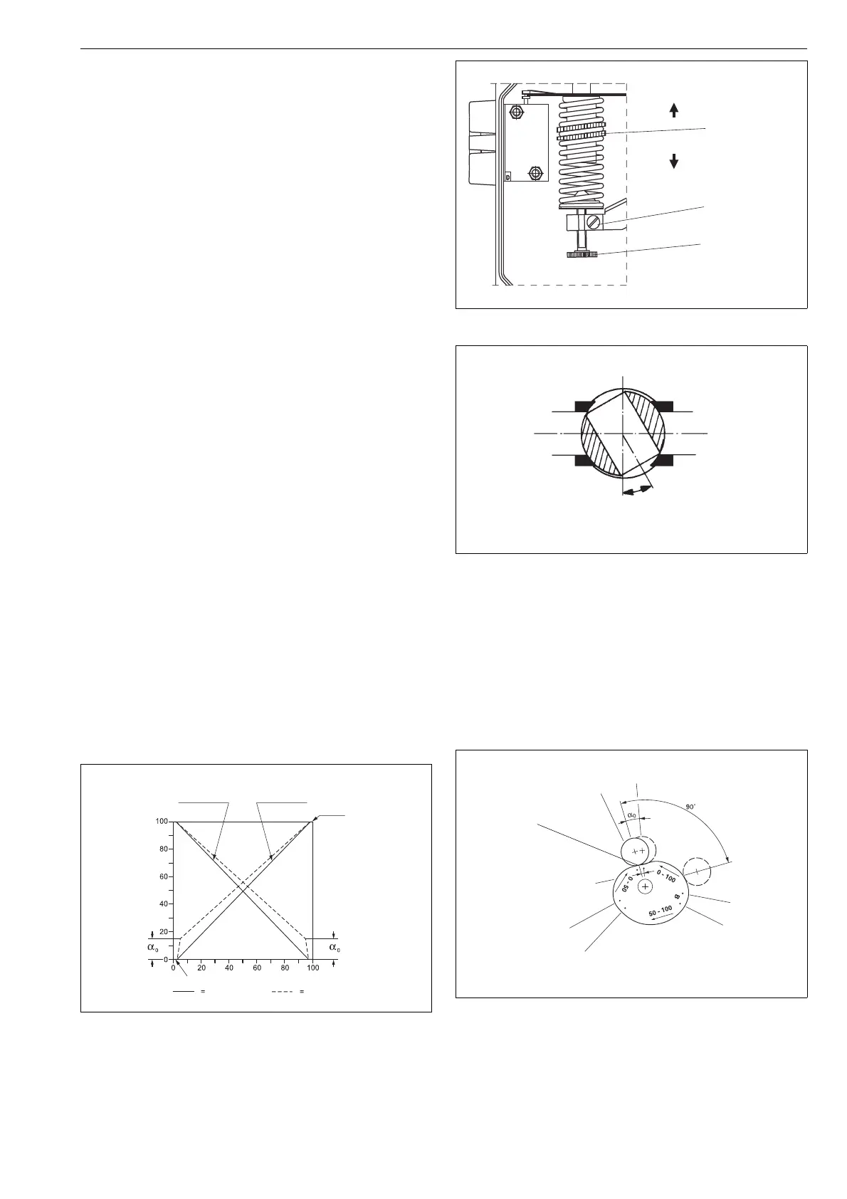
Fig. 10 Dead angle
Fig. 11 Shift on circumference of cam equal to dead angle
range increases
range
range decreases
screw (56)
zero adjustment (67)
adjustment (60.3)
segment D
segment C
segment E
shift
Roller contact point when
the ball is completely closed
 Loading...