9
CHAPTER 2
The M2D and M2D-Sub loudspeakers use sophisticated
amplication and protection circuitry to produce
consistent and predictable results in any system design.
This chapter will help you understand and harness the
power of the M2D and M2D-Sub amplier and audio
systems.
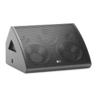
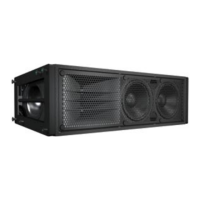
The rear panels of the M2D and M2D-Sub loudspeakers
(Figures 2.1 and 2.2) provide AC connection, audio input,
loop out and an interface to the RMS communications
module.
�
�
Figure 2.1. The user panel of the M2D loudspeaker
THIS APPARATUS MUST BE EARTHED.
REFER SERVICING TO QUALIFIED PERSONNEL.
UND REPARATUR NUR DURCH ELEKTROF�CHKRAFTE
95-125V ~ 208-235V~
INTERNES NE SONT AUTORISEES QU'AU
Auto-Voltage Select
PERSONNEL TECHNIQUE QUALIFI…
NO OPERATOR SERVICEABLE PARTS INSIDE.
Turn on 165V~ Turn off 264V~
Turn on 85V~ Turn off 134V~
Operational Voltage Range:
1400W RMS MAX 1400W RMS MAX
50-60Hz 50-60Hz
ENTRETIENET REPARATIONS
W
i
n
k
S
e
r
v
i
c
e
A
c
t
iv
i
t
y
R
es
e
t
U.K. WARNING:
ATTENTION:
THIS PRODUCT MUST BE GROUNDED
This surface may reach high tempuratures white in use.
To ensure proper operation, allow at least 6 inches
AUTHORIZADO A PERSONAL T…CNICO CALIFICO
To reduce the risk of electric shock do not remove cover.
GEH�USE NICHT OFFENE WARTUNG
ACCESO INTERNO SOLO
To reduce the risk of fire or electric shock
Refer servicing to qualified personnel.
No operator or serviceable parts inside.
do not expose this appliance to rain or moisture.
clearance from this surface and adequate ventilation.
ATENCI”N:
ACHTUNG:
WARNINGS:
Meyer Sound, Berkeley, CA USA
Figure 2.2. The user panel of the M2D-Sub loudspeaker
AUDIO INPUT
The M2D and M2D-Sub loudspeakers present a 10 kOhm
balanced input impedance to a three-pin XLR connector
with the following connectors:
Pin 1 — 220 kOhm to chassis and earth ground (ESD
clamped)
Pin 2 — Signal ( + )
Pin 3 — Signal ( - )
Case — Earth (AC) ground and chassis
Pins 2 and 3 carry the input as a differential signal; pin
2 is hot relative to pin 3, resulting in a positive pressure
wave when a positive signal is applied to pin 2. Pin 1 is
connected to earth through a 220 kOhm, 1000 pF, 15 V
clamp network. This ingenious circuit provides virtual
ground lift for audio frequencies, while allowing unwanted
signals to bleed to ground.
Use standard audio cables with XLR connectors for
balanced signal sources. Make sure that pin 1 (shield) is
always connected on both ends of the cable. Telescoping
grounding schemes are not recommended.
CAUTION: Ensure that all cabling carrying
signals to M2D or M2D-Sub loudspeakers
in an array is wired correctly: Pin 1 to Pin 1, Pin 2
to Pin 2, and so forth, to prevent the polarity from
being reversed. Any number of loudspeakers —
even one in the array — with reversed polarity will
result in severe degradation in frequency response
and coverage.
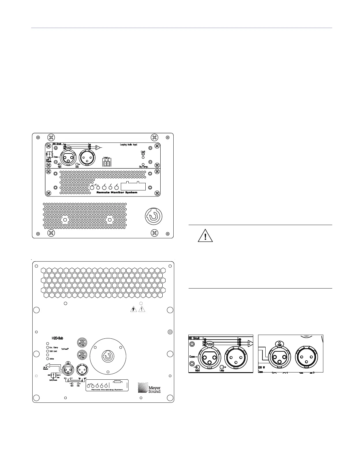
Audio signals can be daisy-chained using the loop output
connector on the user panel (Figure 2.3). A single source
can drive multiple M2D or M2D-Sub loudspeakers with a
paralleled input loop, creating an unbuffered hard-wired
loop connection.
�
�
THIS APPARATUS MUST BE EARTHED.
REFER SERVICING TO QUALIFIED PERSONNEL.
UND REPARATUR NUR DURCH ELEKTROF�CHKRAFTE
95-125V ~ 208-235V~
INTERNES NE SONT AUTORISEES QU'AU
Auto-Voltage Select
PERSONNEL TECHNIQUE QUALIFI…
NO OPERATOR SERVICEABLE PARTS INSIDE.
Turn on 165V~ Turn off 264V~
Turn on 85V~ Turn off 134V~
Operational Voltage Range:
1400W RMS MAX 1400W RMS MAX
50-60Hz 50-60Hz
ENTRETIENET REPARATIONS
W
i
n
k
S
e
r
v
i
ce
A
c
t
i
v
i
ty
R
e
set
U.K. WARNING:
ATTENTION:
THIS PRODUCT MUST BE GROUNDED
This surface may reach high tempuratures white in use.
To ensure proper operation, allow at least 6 inches
AUTHORIZADO A PERSONAL T…CNICO CALIFICO
To reduce the risk of electric shock do not remove cover.
GEH�USE NICHT OFFENE WARTUNG
ACCESO INTERNO SOLO
To reduce the risk of fire or electric shock
Refer servicing to qualified personnel.
No operator or serviceable parts inside.
do not expose this appliance to rain or moisture.
clearance from this surface and adequate ventilation.
ATENCI”N:
ACHTUNG:
WARNINGS:
Meyer Sound, Berkeley, CA USA
Figure 2.3. M2D and M2D-Sub user panel audio input connectors
CHAPTER 2: AMPLIFICATION AND AUDIO
 Loading...