29
APPENDIX B
APPENDIX B
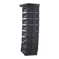
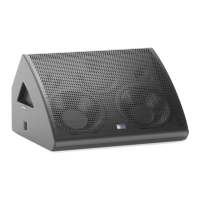
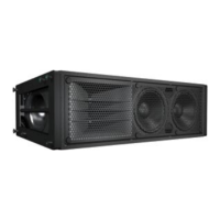
M2D SPECIFICATIONS
ACOUSTICAL
Note: The low-frequency power response of the system will increase according to the length of the array.
Operating frequency range 60 Hz - 16 kHz
Note: Recommended maximum operating frequency range. Response depends upon
loading conditions and room acoustics.
Frequency response 70 Hz - 14 kHz ±4 dB
Note: Free eld, measured with 1/3 octave frequency resolution at 4 meters.
Phase response 650 Hz - 12 kHz ±45°
Maximum peak SPL 136 dB
Note: Measured with music at 1 meter.
Dynamic range >110 dB
Horizontal coverage 90°
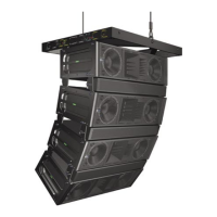
Vertical coverage Varies, depending on array length and conguration.
Acoustical crossover 575 Hz
Note: At this frequency, the mid- and high-frequency transducers produce equal sound
pressure levels.
TRANSDUCERS
Low frequency Two 10" cone drivers with neodymium magnets
Nominal impedance: 4 Ω
Voice coil size: 2"
Power-handling capability: 400 W (AES)
Note: Power handling is measured under AES standard conditions: transducer driven
continuously for two hours with band limited noise signal having a 6 dB peak-average ratio.
Note: To eliminate interference at short wavelengths, the two 10" drivers work in combination at low frequencies (60 Hz
– 350 Hz). At mid frequencies (350 Hz – 575 Hz) only one cone driver is fed from the crossover to maintain optimal polar
and frequency response characteristics.
High frequency One 4" diaphragm compression driver
Nominal impedance: 8 Ω
Voice coil size: 4"
Exit size: 1.5"
Power-handling capability: 250 W (AES)
Note: Power handling is measured under AES standard conditions: transducer driven
continuously for two hours with band limited noise signal having a 6 dB peak-average ratio.
Note: The driver is coupled to a constant-directivity horn through a proprietary acoustical manifold (REM).
AUDIO INPUT
Type Differential, electronically balanced
Max. common mode range ±15 V DC, clamped to earth for voltage transient protection
Connectors Female XLR input with male XLR loop output or VEAM all-in-one connector (integrates AC,
audio and network)
Input impedance 10 kΩ differential between pins 2 and 3
Wiring Pin 1: Chassis/earth through a 220 kΩ, 1000 pF, 15 V clamp network to provide virtual
ground lift at audio frequencies
Pin 2: Signal +; Pin 3: Signal -
Case: Earth ground and chassis
DC Blocking Differential DC blocking up to max common mode voltage
CMRR >50 dB, typically 80 dB (50 Hz – 500 Hz)
 Loading...