12 13MIDAS DL231 Quick Start Guide
Connecting up
The DL231 I/O unit uses the following leads and connectors:
Primary Analogue Inputs:
Mic/Line Inputs - Balanced XLR connectors - 10K load
Primary Analogue Outputs:
Main Outputs - Balanced XLR connectors - 50R Source
AES50 Connections:
Neutrik EtherCON with status indication
Ethernet Control Connection:
Neutrik EtherCON with status indication
Diagnostics Connection:
9 W Female ‘D’ type connector
Power Connections:
IEC mains inlet – 10
0-240 V AC~50-60 Hz
For further information about the connectors used in conjunction with the
DL231 I/O unit, see Section 5. Connectors.
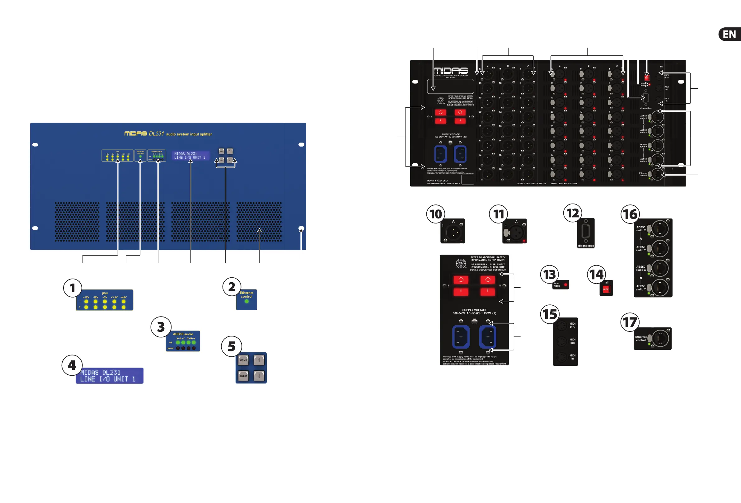
3. Front Panel
(1) The psu panel monitors the two voltage supplies. There are ve yellow
LEDs per voltage supply, and each LED represents a voltage rail. An LED will
illuminate when its respective voltage rail is active.
(2) The Ethernet control panel has a single green LED, wh
ich has three
states of illumination: ashing = active; on = connected; and o =
not connected.
(3) The AES50 audio panel shows the health status of the communications of
the AES50 connections. If the green ok LED is illuminated, communication
is good
. However, if the red error LED is illuminated, there is a problem on
that connection.
(4) LCD Display - 2 x 16 character blue backlit liquid crystal display.
(5) Con guration Control - ‘Menu’, ‘Select’, ‘Up’ and ‘Down’ buttons for
con guring menu items.
(6) There are fou
r air intakes for fan cooling. Do not obstruct.
(7) There are four cut-outs for rack mounting xings.
(8) Unit serial number label.
(9) Ventilation grills, which provide an air outtake for fan cooling of the inside
of the unit.
(10) Male XLR chassis connectors, which provide outputs for line eq
uipment.
Each socket has a red LED that illuminates when mute is on for that output.
(11) Female XLR chassis connectors, which provide inputs for mic/line
equipment. Each socket has a red LED that illuminates when +48 V
phantom power is on for that input.
(1
2) The diagnostics connector is a 9-way D-type connector for connecting a
laptop/PC by service personnel for diagnostics purposes. This is not an
operator function and is only to be used by service personnel.
(13) The boot mode switch selects between normal operation and a
service personnel-only con guration boot mode. It has an adjacent
red LED, which illuminates to show when the unit is in se
rvice only
con guration mode.
(14) The MUTE button mutes all the outputs simultaneously when held down
for longer than one second. It has an integral LED that illuminates when
mute is active.
(15) There are three MIDI (m
usical instrument digital interface) sockets —
MIDI in, MIDI out and MIDI thru — for connection of a MIDI device,
such as a synthesiser. The MIDI in socket receives MIDI data, and the
MIDI thru socket gives out the same MIDI data that is received by the
MIDI in socket. The MIDI out socket gives out MIDI dat
a generated by the
attached MIDAS Digital Console.
 Loading...