14 15MIDAS DL231 Quick Start Guide
(16) Four AES50 audio EtherCON sockets provide connection to the console
and pass audio and control data in both directions. Each socket has a pair
of red and green LEDs, which indicate the following:
• • Green pulsating and red extinguished = valid audio and valid control
data; active link.
• • Green constantly illuminated and red extinguished = valid audio and
valid control data; standby link.
• • Green extinguished and red illuminated = no audio; link has failed.
(17) The Ethernet control EtherCON socket on the rear panel allows Ethernet
control via Cat 5e cable up to 100 m long. This socket has a green LED that
indicates the following:
• • Green LED solid = connected but not active
• • Green LED ashing = active
• • Green LED extinguished = fault or no connection
Mains power
Each mains inlet should be sourced from its own separate
wall-mounted mains outlet socket. Otherwise, both mains
sources must be suitably distributed so as to meet local
safety regulations.
The mains is supplied to the DL231 via dual redundant mains inlets.
(18) Dual redundant power supplies.
(19) Mains on/o isolator switch.
(20) Mains IEC socket.
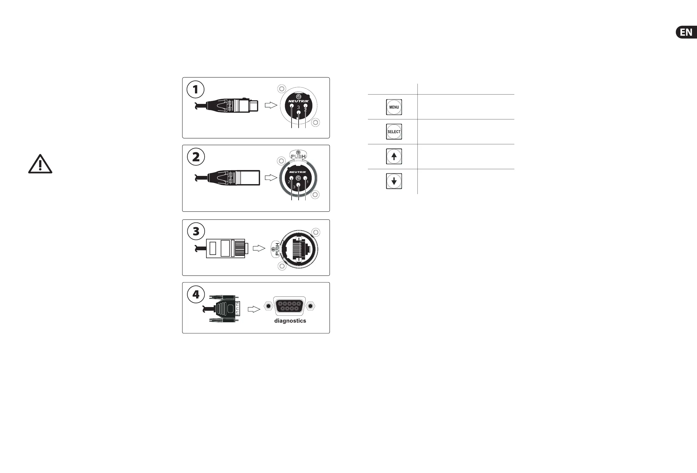
5. Connectors
To ensure the correct and reliable operation of the equipment, only high quality
balanced, screened, twisted pair audio cable should be used. XLR connector
shells should be of metal construction so that they provide a screen when
connected to the console/snake and, where appropri
ate, they should have Pin 1
connected to the cable screen.
(1) Line output audio connector. Female XLR plug and male XLR chassis
connector with the following pinouts: 1 = ground; 2 = hot; and 3 = cold.
(2) Mic/line input audio connector. Male XLR plug and female XLR ch
assis
connector with the following pinouts: 1 = ground; 2 = hot; and 3 = cold.
(3) Ethernet socket. RJ45 plug and EtherCON socket.
(4) Diagnostics. 9-way, D-type plug and socket.
6. Operation
Programming Mode
This chapter describes the programming mode of the DL231 I/O Unit.
Menu navigation
The four programming buttons in the control panel have the following functions.
Navigation buttons Usage
Moves up or down a menu level, or exits programming
mode, depending on the current menu level.
Selects the current option.
Scrolls through the current level of menus/options.
Scrolls through the current level of menus/options in
the opposite direction to the up arrow button.
The menu owcharts on pages 17 through 21 give an overview of all the menus
and their options, and shows you how to navigate your way around them. In the
diagram the menus are shown on the left, and each subsequent lower level is to
the right.
To enter/exit programming mode
To enter programming mode
, press the MENU button and hold down for
approximately two seconds; the default display will change to the top-level
“Select Menu:” display (see “Menus” on this page).
To exit programming mode from any menu display screen, press MENU
repeatedly until yo
u reach the default screen. The unit will exit programming
mode automatically after about 20 seconds of inactivity if none of the
programming buttons are pressed within that time.
To select a menu
In programming mode, scroll to the menu you want by using the up/down arrow
buttons, then press SELECT.
Menus
The eight menus in programming mode are as follows:
1. MicSplit ID – for setting up the unit’s network ID (see “MicSplit ID
Menu” below).
2. AES50 Sync – for selecting the method for synchronizing the AES50
(see “AES50 Sync Menu” below).
3. Output Source – for setting up the output signal routing fr
om the unit’s
analogue or AES50 digital inputs.
4. 48 V Control – for controlling the source of 48 V phantom power.
5. Sample Rate – allows you to set the unit’s sample rate (48k or 96k
sample rates).
6. AES50 Status – lets you view/clear the AES50 values.
7. S/
W Version – for viewing the unit’s software version number.
8. Reset All – lets you reset all settings to default.
In programming mode the four programming buttons in the control panel are
used to navigate and select options from a number of menus, which let you set
up the unit and view inf
ormation.
 Loading...