X X Y E F1F1 F2F2 E E FORCED ON EMG.STOP L N N
(GB845/ST3.9*25)
~
0 0 ~ 15
ON
1
2
3
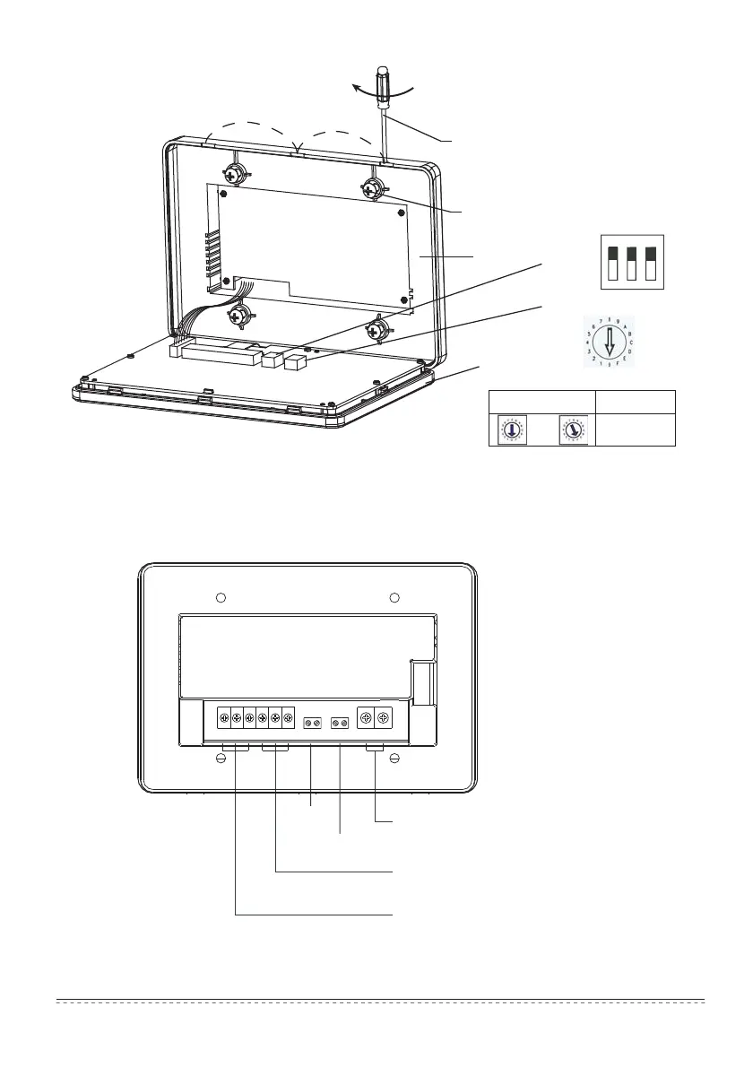
Insert the flathead screwdriver into the
concave on the upper side of the box,
and rotate slightly to open the upper cover(3 places).
Fix the screws of the centralized controller
Base
Front cover
Address dial code
Dial code
Dial code position
Address range
Fig. 1.2 Installation diagram
Forced on
switch
Emergency
stop switch
L、N terminals
(198V~242V)/(50/60Hz)
Communication terminal with computer
Communication terminal with air conditioner
Fig.1.3 Terminal instruction of centralized controller
Installation & Owner‘s Manual
4

 Loading...