18 Specifications subject to change without notice. 32801002001
ELECTRICAL DATA
Table 12 — Electrical Data
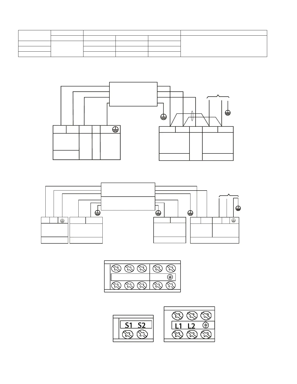
CONNECTION DIAGRAMS
Fig. 55 — Connection Diagram (size 24K)
Fig. 56 — Connection Diagram (sizes 36K and 48K)
Fig. 57 — Control and Power Terminal on Indoor Unit (size 24K)
Fig. 58 — Control and Power Terminals on Indoor Unit (sizes 36K to 48K)
UNIT SIZE
INDOOR FAN MAX FUSE CB AMP
V-PH-HZ FLA HP W
Refer to outdoor unit installation instructions –
Indoor unit powered by the outdoor unit
24
208-230/1/60
5 0.20 120
36 5 0.42 250
48 5 0.65 400
2(L2)
3(S) 1(L1)
2 (L2)
CONNECTING CABLE
OUTDOOR TO INDOOR
Indoor Unit
Power Supply
208-230-1-60
Indoor
Signal
High
GND
Ground
Power to
Indoor Unit
Voltage
Indoor
SignaLl
High
Voltage
L1
L2
FIELD POWER SUPPLY
Indoor Unit
Power Supply
Nonpolar RS-485
communication
Nonpolar RS-485
Low voltage
communication
Outdoor Unit
Power Supply
SHIELDED WIRE CONNECTING
OUTDOOR TO INDOOR
To Indoor Unit
Power Supply
S1
S2
L1
L1
L2
L2
(S1)
(S2)
CONNECTING CABLE
OUTDOOR TO INDOOR
 Loading...