37
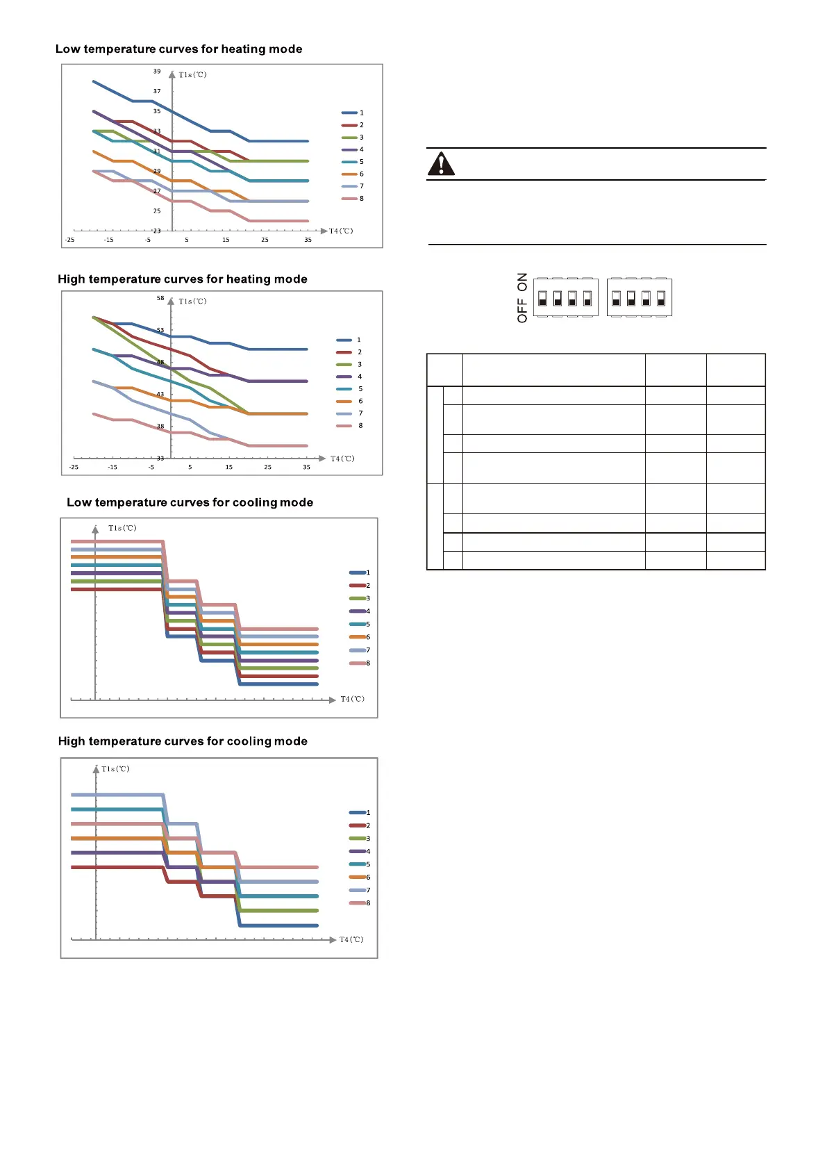
10.2 DIP switch settings overview
1 2 3 4 1 2 3 4
Description ON
S1 S2
OFF
1 Selection of refrigerant pipe length 50m
5m
2 Installed
Installed
Not installed
Installed
Not installed
3 Installed
4 Installed
1 Not installed
2 /
DIP switch 13 is located on the hydraulic module main control board
(see "9.2.3 main control board of hydraulic module")
and allows configuration of additional heating source thermistor
installation, the second inner backup heater installation, etc.
Switch off the power supply before opening the switch box
service panel and making any changes to the DIP switch
settings.
DIP
switch
/
Backup heater outlet temperature
thermistor installation
The first inner backup heater installation
The second inner backup heater
installation
Additional heating source outlet
temperature thermistor installation
/
3 //
/
4 //
/
WARNING
S1
S2
3
8
13
18
23
-5 5 15 2 5 35 45
15
17
19
21
23
25
27
-5 5 15 25 35 45
 Loading...