Do you have a question about the Midea MSG-07CRN2 and is the answer not in the manual?
| Brand | Midea |
|---|---|
| Model | MSG-07CRN2 |
| Category | Air Conditioner |
| Language | English |
General safety instructions to prevent injury and property damage during operation and installation.
Important warnings regarding installation and usage to prevent hazards like fire or electric shock.
Important cautions regarding refrigerant leakage, installation, and maintenance procedures.
Details the functions and controls of the indoor unit, including operation modes and indicators.
Details the functions and features of the outdoor unit, such as protection and special kits.
Provides dimensional data for the indoor unit with a table of measurements.
Provides dimensional data for the outdoor unit with a table of measurements.
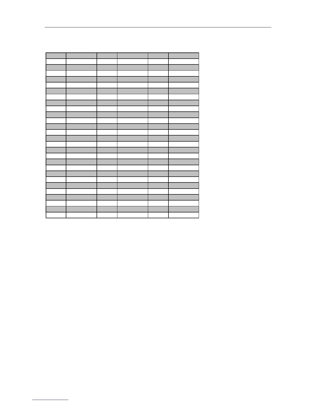
Technical specifications including power, capacity, and components for models MSG-07CRN2, MSG-07HRN2, MSG-09CRN2.
Technical specifications including power, capacity, and components for models MSG-09HRN2, MSG-12CRN2, MSG-12HRN2.
Technical specifications including power, capacity, and components for models MSG-16CRN2, MSG-16HRN2, MSG-18CRN2.
Technical specifications including power, capacity, and components for models MSG-18HRN2, MSG-21CRN2, MSG-21HRN2.
Diagram illustrating the refrigerant flow for cooling operation only.
Diagram illustrating the refrigerant flow for heat pump operation.
Chart showing operating limits for cooling based on outdoor and indoor temperatures.
Chart showing operating limits for heating based on outdoor and indoor temperatures.
Electrical schematic of the unit's internal circuits, showing component connections.
Wiring diagram for cooling mode, models MSG-07CR, MSG-09CR, MSG-12CR.
Wiring diagram specific to the MSG-16CR model.
Wiring diagram for models MSG-18CR and MSG-21CR.
Wiring diagram for models MSG-07HR, MSG-09HR, MSG-12HR.
Wiring diagram for models MSG-16HR, MSG-18HR, MSG-21HR.
Specifies torque values for installation fittings based on pipe diameter.
Guidelines for selecting and connecting power cords based on unit capacity.
Details on maximum pipe length and elevation differences and refrigerant addition.
Procedure for removing air from the refrigeration piping to ensure proper function.
Procedure for recovering refrigerant during re-installation to prevent loss.
Process for purging air from the system after re-installation.
Procedure for balancing refrigerant levels in the system.
Method for creating a vacuum in the refrigerant system to remove moisture and air.
Steps for adding the correct amount of refrigerant to the system.
Cooling and heating capacity data for model MSG-07CRN2.
Cooling and heating capacity data for model MSG-07HRN2.
Cooling and heating capacity data for model MSG-09CRN2.
Cooling and heating capacity data for model MSG-09HRN2.
Cooling and heating capacity data for model MSG-12CRN2.
Cooling and heating capacity data for model MSG-12HRN2.
Cooling and heating capacity data for model MSG-16CRN2.
Cooling and heating capacity data for model MSG-16HRN2.
Cooling and heating capacity data for model MSG-18CRN2.
Cooling and heating capacity data for model MSG-18HRN2.
Cooling and heating capacity data for model MSG-21CRN2.
Cooling and heating capacity data for model MSG-21HRN2.
Specifies operating conditions for electronic controls, including voltage and temperature.
Explains symbols used in electronic functions and controls for clarity.
Lists and describes various operational functions of the unit, such as remote receiving and timers.
Details the various protection mechanisms of the unit, like compressor restart delay and sensor protection.
Describes the operation when only the fan is active, with speed settings.
Explains the cooling operation mode and the function of the 4-way valve.
Details the dehumidification operation, including 4-way valve status and fan actions.
Explains the heating operation mode, including 4-way valve and fan actions.
Describes heating mode operations including fan control and anti-cold wind.
Explains automatic fan speed control in heating mode based on temperature.
Details protection against high evaporator temperatures in heating mode.
Describes the defrosting function during heating, including conditions and timing.
Explains automatic mode selection based on temperature differences.
Describes how to activate a forced cooling operation for quick cooling.
Details the sleep mode function for energy saving, with temperature adjustments.
Explains automatic temperature adjustment in sleep mode for cooling, heating, and auto.
Explains automatic restart after power failure, restoring previous settings.
Describes the optional anion function, which starts with the indoor fan.
Lists key parameters like current ratings and temperature protection points for various models.
Explains the indicators on the display board and their meanings.
Table correlating failure phenomena with indicator status for cooling and heat pump modes.
Flowchart for diagnosing operational problems related to power and PCB.
Addresses issues with the unit resetting during operation due to voltage instability.
Troubleshooting for specific lamp status combinations indicating a fault.
Troubleshooting for specific lamp status combinations indicating a fault.
Troubleshooting for specific lamp status combinations indicating a fault.
Troubleshooting for specific lamp status combinations indicating a fault.
Troubleshooting for specific lamp status combinations related to zero-signal errors.
Table showing resistance values of temperature sensors at various temperatures.