MCAC-VTSM-2015-10 R410A All DC Inverter V5 X Series 50Hz
Troubleshooting 135
ENC1: Outdoor unit address setting
Only 0, 1, 2, 3 are available.
0 is for master unit; 1, 2, 3 are for slave units
ENC2: Outdoor unit capacity setting
Only 0, 1, 2, 3, 4, 5 are available.
0: 8HP; 1: 10HP; 2: 12HP; 3: 14HP; 4: 16HP; 5: 18HP
ENC4: Network address setting
Only 0, 1, 2, 3, 4, 5, 6, 7 are available.
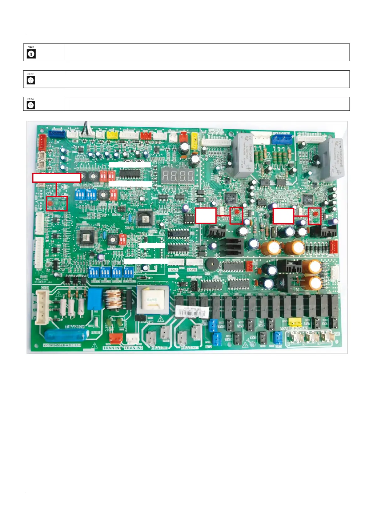
2.3 LED on main control board instructions
LED1: Power supply indicator. The lamp will keep on if the power supply is normal.
LED2: Running indicator. The lamp will keep on if the system running is normal, the lamp will flash if the
system has problem.
LED3: Malfunction indicator of network centralized control chip. The lamp will flash if three-phase sequence
protection or communication errors (communication between indoor units and outdoor units, communication
among indoor units, communication among chips).
LED4: Running indicator of inverter module. The lamp will keep on if the compressor is running.
LED5: Malfunction indicator of inverter module. LED5 will keep on and the LED4 will flash if the inverter
module is faulty and the error code will be displayed on digital tube by pressing the query button.
LED6: Running indicator of inverter module. The lamp will keep on if the compressor is running.
LED7: Malfunction indicator of inverter module. LED7 will keep on and the LED6 will flash if the inverter
module is faulty and the error code will be displayed on digital tube by pressing the query button.
ENC1
ENC3
S12
S3
S7
S1
ENC2
S4
S2
S5
S6
ENC4
S10
LED3, LED2, LED1
LED7
LED6
LED5
LED4
 Loading...