8.3 Communication Wiring
Communication wiring design and installation should adhere to the following requirements:
0.75mm
2
three-core shielded cable should be used for communication wiring. Using other types of cable can lead to
interference and malfunction.
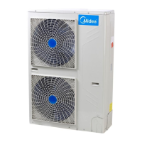
Indoor communication wiring:
The P Q E communication wires should be connected one unit after another in a daisy chain from the outdoor unit
to the final indoor unit. At the final indoor unit, a 120Ω resistor should be connected between the P and Q
terminals. After the final indoor unit, the communication wiring should NOT be continued back to the outdoor
unit – that is, do not attempt to form a closed loop.
The P and Q communication wires should NOT be grounded.
The shielding nets of the communication wires should be connected together and grounded. Grounding can be
achieved by connecting to the metal casing adjacent to the P Q E terminals of the outdoor unit electrical control
box.
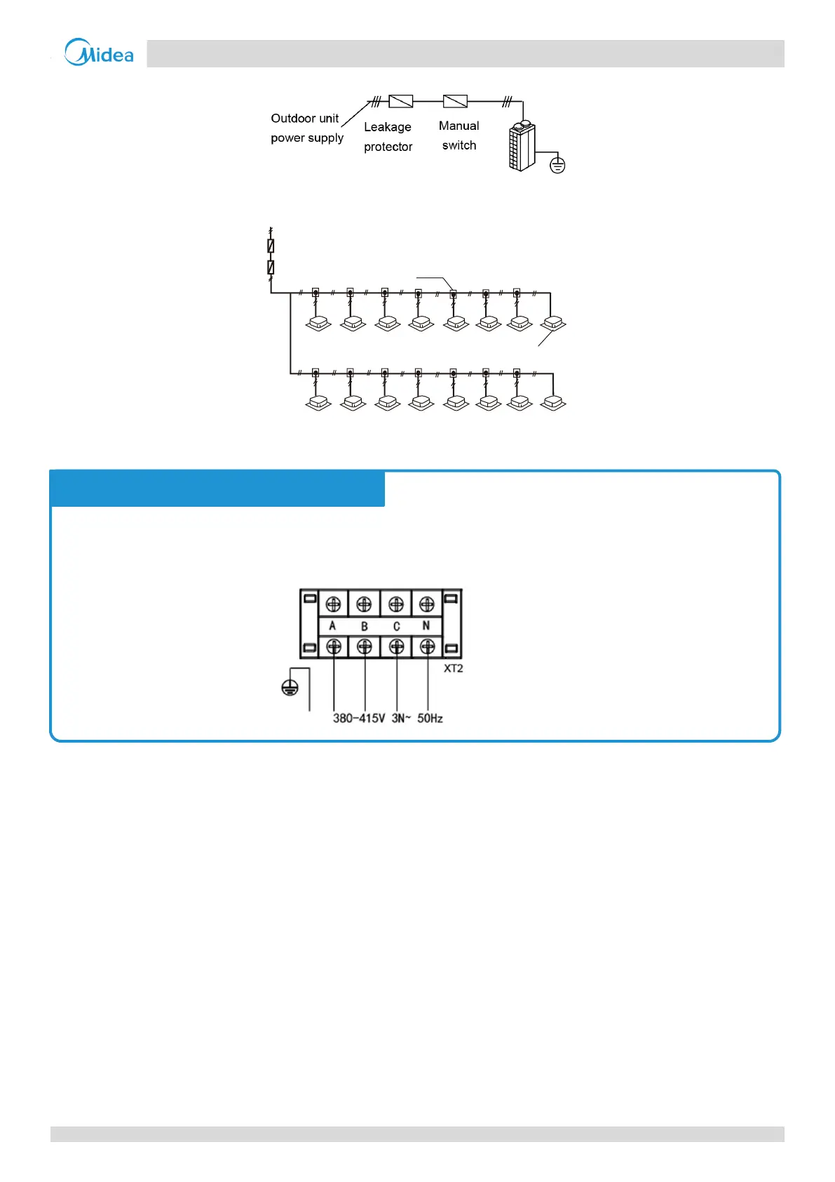
The 3-phase, 380-415V, 50Hz of power supply should be connected to the outdoor unit power supply terminals as

 Loading...