3 Refrigerant Piping Design
3.1 Design Considerations
Refrigerant piping design should take account of the following considerations:
The amount of brazing required should be kept to a minimum.
On the two inside sides of the first indoor branch joint (“A” in Figures 3-3.2, 3-3.3 and 3-3.4) the system should, as far
as possible, be equal in terms of number of units, total capacities and total piping lengths.
3.2 Material Specification
Only seamless phosphorus-deoxidized copper piping that complies with all applicable legislation should be used. Temper
grades and minimum thicknesses for different diameters of piping are specified in Table 3-3.1.
3.3 Permitted Piping Lengths and Level Differences
The piping length and level difference requirements that apply are summarized in Table 3-3.2 and are fully described as
follows (refer to Figure 3-3.2):
1. Requirement 1: The total length of piping in one refrigerant system should not exceed 150m.
2. Requirement 2: The piping between the farthest indoor unit (N6) and the outdoor unit should not exceed 100m (actual
length) and 110m (equivalent length). (The equivalent length of each branch joint is 0.5m.)
3. Requirement 3: The piping between the farthest indoor unit (N6) and first indoor branch joint (A) should not exceed
40m in length.
4. Requirement 4: Indoor auxiliary pipes (a to f) should not exceed 15m in length.
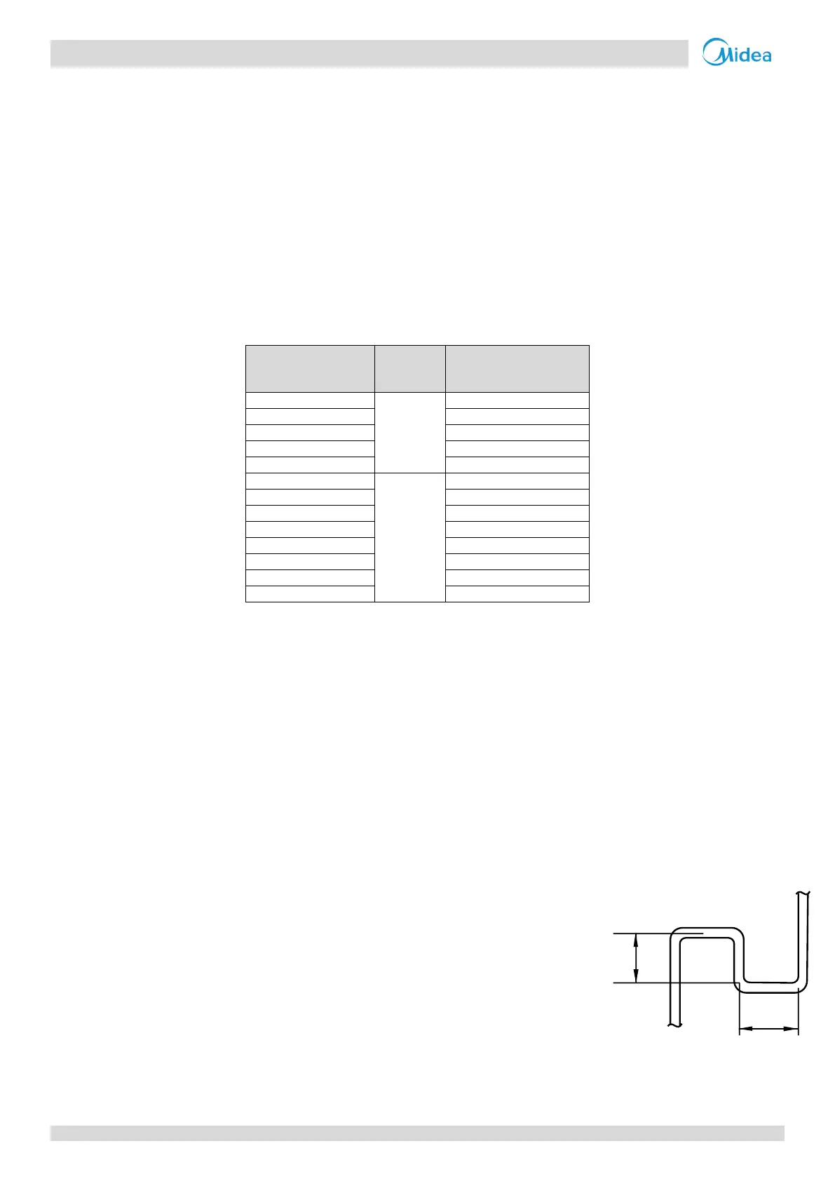
5. Requirement 5: The largest level difference between indoor unit and outdoor
unit should not exceed 50m (if the outdoor unit is above) or 40m (if the outdoor
unit is below). Additionally: If the outdoor unit is above and the level difference
is greater than 20m, it is recommended that an oil return bend with dimensions
as specified in Figure 3-3.1 is set every 10m in the gas pipe of the main pipe.
6. Requirement 6: The largest level difference between indoor units should not
exceed 15m.

 Loading...