1.
2.
3.
4.
5.
6.
Use the MikroTik smartphone app to configure your router in the field, or to apply the most basic initial settings for your MikroTik home access point.
Scan QR code and choose your preferred OS.
Install and open application.
By default, the IP address and user name will be already entered.
Click Connect to establish a connection to your device through a wireless network.
Choose Quick setup and application will guide you through all basic configuration settings in a couple of easy steps.
An advanced menu is available to fully configure all necessary settings.
Powering
The device accepts power from the power jack or from the first Ethernet port (Passive PoE):
Direct-input power jack (5.5 mm outside and 2 mm inside, female, pin positive plug) accepts 10-30 V DC.
First Ethernet port accepts passive Power over Ethernet accepts 12-30 V DC.
The power consumption under maximum load can reach 5 W.
The Ether5 port supports PoE output for powering other RouterBOARD devices. The port has an auto-detection feature, so you can connect Laptops and
other non-PoE devices without damaging them. The PoE on Ether5 outputs approximately 2 V below input voltage and supports up to 0.58A (So provided
24 V PSU will provide 22V/0.58 A output to the Ether5 PoE port).
Configuration
Once logged in, we recommend clicking the "Check for updates" button in the QuickSet menu, as updating your RouterOS software to the latest version
ensures the best performance and stability. For wireless models, please make sure you have selected the country where the device will be used, to
conform with local regulations.
RouterOS includes many configuration options in addition to what is described in this document. We suggest starting here to get yourself accustomed to
the possibilities: . In case IP connection is not available, the Winbox tool ( ) can be used to connect to the MAC address https://mt.lv/help https://mt.lv/winbox
of the device from the LAN side (all access is blocked from the Internet port by default).
For recovery purposes, it is possible to boot the device for reinstallation, see section .Buttons and Jumpers
Mounting
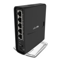
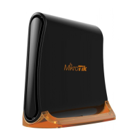
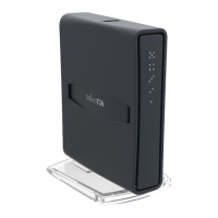
The device is designed to be used indoors and placed on a flat surface with all needed cables connecting to the front of the unit.
Alternatively, the unit can be mounted on the wall, mounting points are located on the bottom side of the device, screws are not included in the package.
Screws with size 4x25 mm fit nicely, depending on your wall structure you can use dowels 6x30 mm and 6 mm drill bit if needed.
When mounting on the wall, please ensure that cable feed is pointing downwards.
We recommend using Cat6 shielded cables.
Warning! This equipment should be installed and operated with a minimum distance of 20 cm between the device and your body. Operation of this
equipment in the residential environment could cause radio interference.
Extension Slots and Ports
Five individual 10/100 Ethernet ports, supporting automatic cross/straight cable correction (Auto MDI/X), so you can use either straight or cross-
over cables for connecting to other network devices.
Integrated Wireless 2.4 GHz and 5 GHz 802.11 a/b/g/n/ac, simultaneous dual-band radio with onboard PIF antennas, max gain 1.5 dBi.
Buttons and Jumpers
 Loading...