RouterBOARD 493 Series User's Manual
Appendix
Connector Index
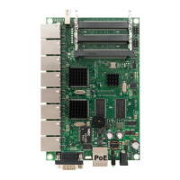
RS232C male DB9 serial port
2 RxD (Receive Data)
3 TxD (Transmit Data)
5 GND
7 RTS (Request to Send)
8 CTS (Clear to Send)
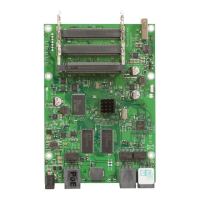
MiniPCI Type type IIIA/B connector 1 (lowest)
MiniPCI Type type IIIA/B connector 2 (middle)
MiniPCI Type type IIIA/B connector 3 (top)
RJ45 Fast Ethernet 100Base-TX port LAN1 with passive PoE extension
RJ45 Fast Ethernet 100Base-TX port LAN2-9 (no PoE)
Power jack (10..28 V DC, positive contact is the central pin)
Two DC Fan 3.3V connectors (alternating)
1 GND
2 +3.3 V DC
3 Rotation speed feedback
Two DC Fan Line connectors (alternating)
1 GND
2 +12/+24 V DC (same as input voltage)
3 Rotation speed feedback
One USB 2.0 (RB493G only)
Button Index
S3 Software Reset 1 button. Loads the Primary boot loader
RESET Software Reset 2 jumper. Resets RouterOS settings
Ethernet Cables
Note: When using the MikroTik Gigabit PoE injector, PoE is passed on pins 4,5 (+) and 7,8 (-).When using
other PoE injectors, power can be passed on any other pins, depending on PoE injector model.
RJ45
Pin
Color Function
(100Mbit)
Function
(1Gbit)
RJ45 pin for Straight cable
(MDI, EIA/TIA568A)
RJ45 pin for Crossover cable
(MDI-X, EIA/TIA568B)
1 Green TX+ Data Data A+ 1 3
2 Green/White TX- Data Data A- 2 6
3 Orange RX+ Data Data B+ 3 1
4 Blue - Data C+ 4 4
5 Blue/White - Data C- 5 5
6 Orange/White RX- Data Data B- 6 2
7 Brown - Data D+ 7 7
8 Brown/White - Data D- 8 8
10
 Loading...
