RouterBOARD SXT Series User's Manual rev. 6
The command disconnects power for USB port. However, the same power source is used for the Wireless
power amplifier. It means, that during USB power reset wireless signals are transmitted with reduced power.
It may cause small interruption of wireless communication.
User's Guide
First use
The SXT device is assembled and ready to use:
• Plug the supplied PSU into a power socket, and connect it to the supplied PoE injector
• Connect one end of the injector to a switch or any other device, and the other end to Ethernet cable
leading to the SXT device
• Connect to the SXT device with SSH or Winbox to configure it. See this document for details:
http://wiki.mikrotik.com/wiki/Manual:First_time_startup
• Configure RouterOS according to the manual:
http://wiki.mikrotik.com/wiki/Category:Manual
Configuration note: Wireless interface is disabled by default, you need to connect with any of the above
methods and enable and configure it. To use both chains, you need to enable HT TX/RX chains in the HT tab
in the RouterOS Wireless configuration.
Grounding
It is recommend to use a FTP (foil screened twisted pair) cable – in this case, one end of the cable would be
plugged into the SXT, the other end of the cable will be connected to the buildings grounding installation. If
possible, also connect a grounding wire to the provided grounding connection behind the SXT case door.
Powering
• Power over Ethernet (PoE) on the Ethernet port:
8..30V DC (12..28 V suggested) non-standard PoE powering support. 24V PSU is supplied with the
device
RouterBOARD SXT series boards are compatible with non-standard (passive) Power over Ethernet injectors
(except power over datalines) and accept powering over up to 100m (330 ft) long Ethernet cable connected
to the Ethernet port (J4). The board does not work with IEEE802.3af compliant 48V power injectors.
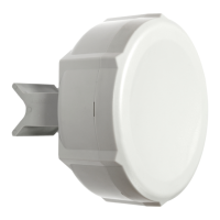
Mounting
With the clip pointed forward, slide the mounting bracket onto the rail on the bottom of the case, until the
clip clicks into place. Make sure the clip is securely holding the mounting bracket in place.
The SXT comes bundled with a hose clamp - guide the clamp through the opening in the bracket and around
the pole where it will be mounted. Tighten the hose clamp screw when alignment is complete. Two screw
holes are provided as additional security against accidental bracket movement.
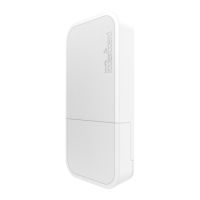
The SXT must be mounted with the door pointing downwards, to avoid moisture coming into the box. The
image shows the only correct way to mount the device. Small holes are located on the bottom to
provide ventilation and exit for condensate:
6
Top
Bottom
 Loading...