4-12 Hardware Principle
4.4 Monitor
Control board
Inverter
board
Key board
Photographic
board
Storage
board
LCD screen
I/O interface board
+12V
+12V
Light control
ON/OFF
Key
signal
+5V DVI I2C
LVDS 3.3V 3.3V 3.3VI2C
sensitive
signal
monitor
High-
voltage
Power signal
Control signal
Video signal
+12V
Speakers
( left/right(
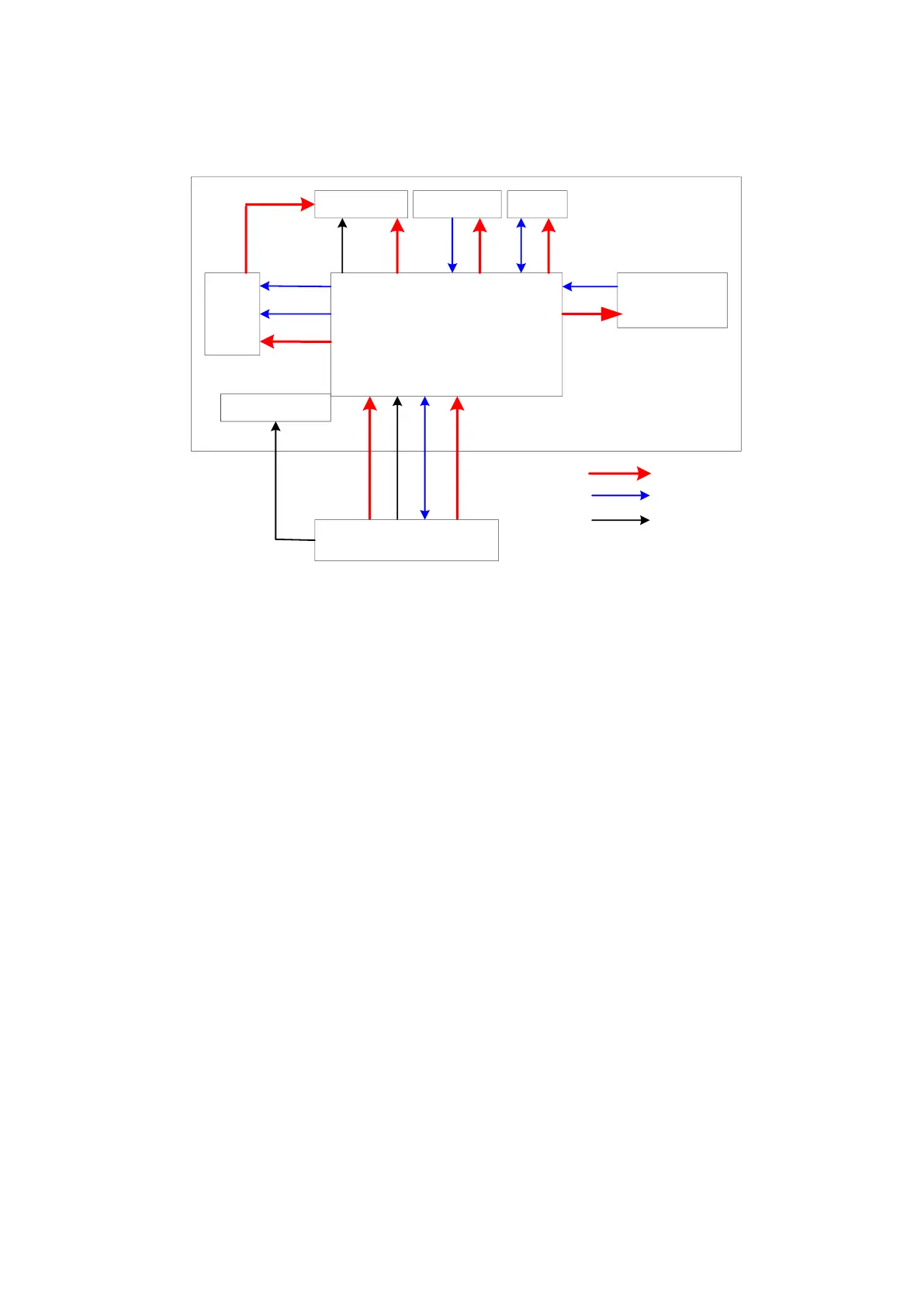
Figure 4-12 Principle Diagram of Monitor
Monitor mainly consists of the control board, inverter board, LCD screen, photographic
board, storage board, OSD key board..
Functions include:
Control board is the main unit of monitor; it transfers input of DVI to LVDS signal
and output the signal to LCD screen, as well as monitors other boards and
signals.
The inverter board generates high voltage to illuminate backlight of LCD, and it is
controlled by control switch and light adjustment on the control board.
Storage board stores color temperature and gamma correction data, and use
them in match with LCD screen to guarantee the display effect consistency; for
the first time of installation or replacing the control board or LCD board, related
parameters should be updated in the control board, Refer to 6.7 Display
Parameter Setting.
The photographic board monitors the brightness of the LCD screen backlight,
and control board adjust the LCD screen backlight brightness according to the
feedback current value, so that LCD screen brightness can be stable when
different temperature or transfer efficiency of the light tube changes.
User operation is accepted through key board, and the control board displays
the menu so that user can adjust some monitor parameters.
CPU module communicates with the monitor using the I2C port, and monitor
parameters can be adjusted.
The speakers are located on both sides of the monitor, the driving signal of
which is from the IO interface board.
 Loading...


