Transducers and Biopsy
12-16
No. Name Description
10 V-shaped cover
Determines the guiding hole together with the V-shaped
guiding block. It can be opened and closed.
11 Angle block
Determines the angle of the biopsy; different specifications
of blocks can be used
12
Angle shift sign
(25°, 35°, 45°)
Matches with the biopsy angle
(25°, 35°, 45°)
13 Angle adjusting base There are 3 types of angles available to be adjusted
14 Angle pinch nut Used for fixing the angle lock at a chosen angle
15
Pinch nut of
needle-guided
bracket
Used for locking the needle-guided bracket and the
transducer
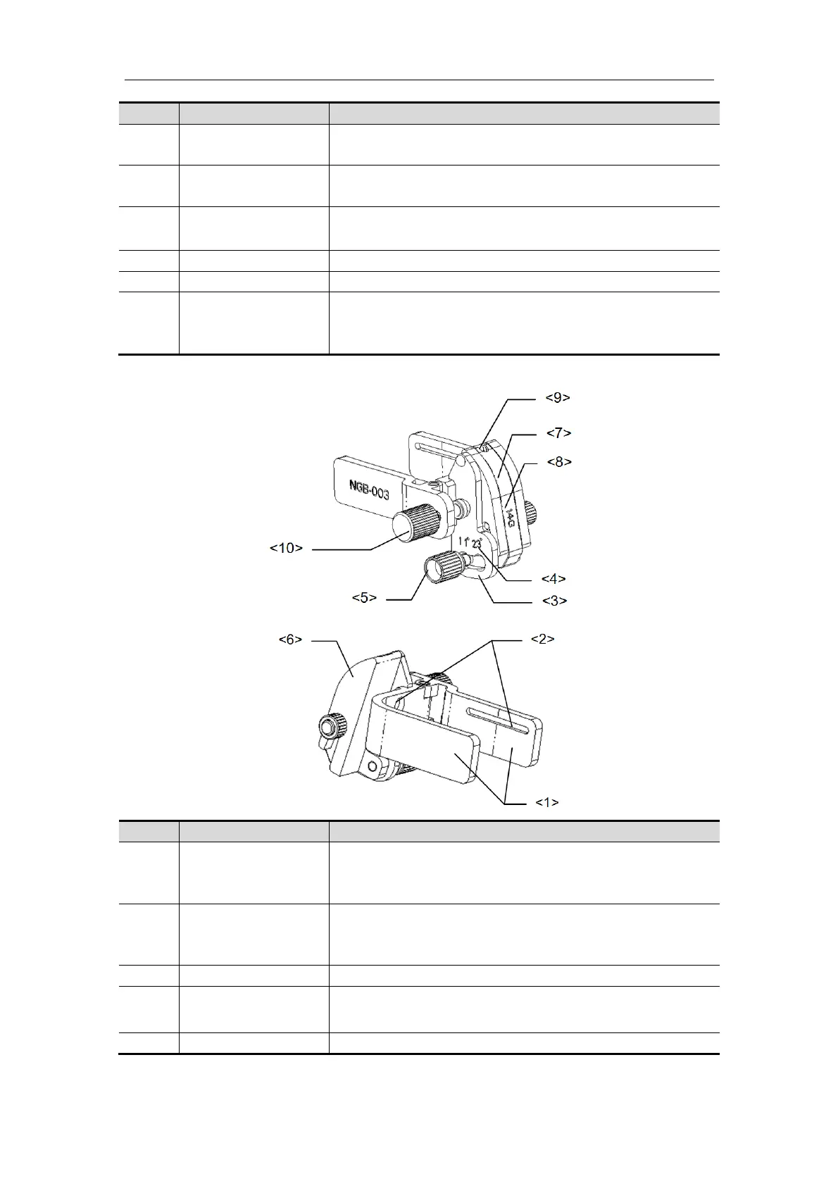
NGB-003 (Metal/needle detachable)
No. Name Description
<1>
Clamp of
needle-guided
bracket
Used for installing the needle-guided bracket on the
transducer
<2>
Groove of the
needle-guided
bracket
Matches with the tab of the transducer
<3> Angle adjusting base There are 2 types of angles available to be adjusted
<4>
Angle shift sign(11°,
23°)
Matched with the biopsy angle(11°, 23°)
<5> Angle pinch nut Used for fixing the angle lock at a chosen angle

 Loading...


