Wiring
2
• JW7: Cut to enable supervision of remote annunciation alarm zone indicators.
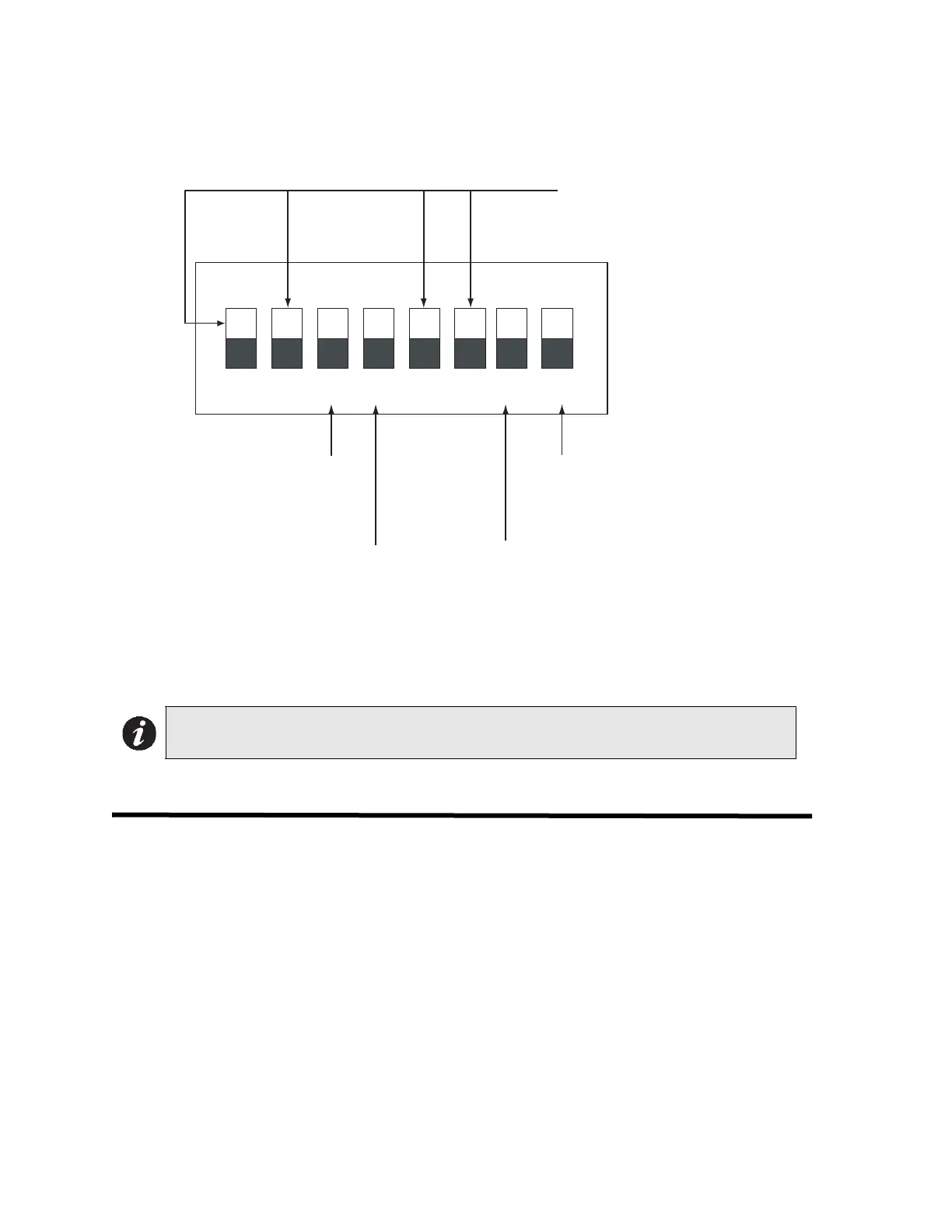
DIP switch DSW1 is used to set the preferred signal zone outputs, the signal silence inhibit, and the
common trouble flash rate.
• Temporal Code: 3 rounds of 0.5 second ON, 0.5 second OFF, then 1.5 second pause.
• Steady: Signal on continuously.
Wiring
Detection Zones
The system has five detection zones. Refer to Figure 3 on page 7 for wiring instruction and to
Figure 4 on page 8 for wire size.
Signal Zone
There are two signal zones available for bells and horns providing 1.7A of signal power. Refer to
Figure 3 on page 7 for wiring instruction and to Figure 5 page 8 on for wire size.
Alarm and Trouble Relays
Alarm and trouble relay contacts are provided. Refer to Figure 6 on page 9 for contact location and
designation.
Note: Any time the DIP switches in DSW1 are positioned (ON or OFF), the panel must
be reset by holding the Reset button for 5 seconds.
1 2 3 4 5 6 7 8
ON
not used
Trouble Buzzer and LED
ON - steady buzzer and LED
OFF - Pulsing Buzzer and LED (default)
Signal Zone 2
ON - steady
OFF - temporal code (default)
ON - 1 minute signal
silence inhibit
OFF - normal signal
silence (default)
Signal Zone 1
ON - steady
OFF - temporal
code (default)
DIP switch DSW1

 Loading...


