Main Display
2
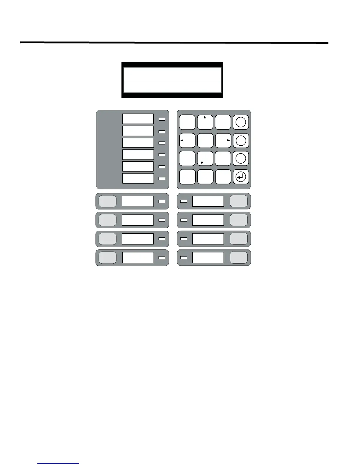
Main Display
Refer to the diagram below for the LCD display, LED indicators, and control buttons locations.
The main display panel on the fire alarm control board consists of:
• Six LED indicators (located just below and to the left of the LCD screen)
• 16 program buttons or keys consisting of an alphanumeric keypad and LCD screen keys (located just below and
to the right of the LCD screen)
• Eight control buttons and corresponding LEDs (below the alphanumeric keypad)
LED indicators may be amber, red, or green, and may illuminate continuously (steady for alarm), or at one of two
flash rates:
• Fast flash (supervisory): 120 flashes per minute
• Trouble flash (trouble): 20 flashes per minutes
COMMON ALARM
COMMON SUPV
TROUB LE
CPU FAULT
GROUND
FAULT
SYSTEM
RESET
FIRE
DRI LL
ALARM
ACKNOWLEDGE
GE NE RAL
ALARM
S IGNAL
BUZZE R
SILENCE
LAMP
TE S T
BATTERY/CHARGER
AC ON
1 2
ABC
3
DEF
5
JKL
6
MNO
7 8
TUV
9
WXY
* 0
QZ
#
4
GHI
PRS
X
M
?
SYSTEM NORMAL
MAY 01, 2007 02:41AM
COMMON
SILENCE
TROU BLE
 Loading...


