12
en
3. Perform the test run in cooling mode, or connect the connector to the ON side of
SWE on the Indoor controller board. (The drain pump and the fan are forced to
operate without any remote controller operation.) Make sure using a transparent
hose that drain is discharged.
Be sure to turn it back to the former state after work.
4. After confirmation, cancel the test run mode, and turn off the main power. If the
connector is connected to the ON side of SWE, disconnect it and connect it to the
OFF side, and attach the water supply port cover into its original position.
[Fig. 7.3.1] (P.5)
[Fig. 7.3.2] (P.5)
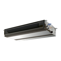
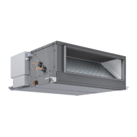
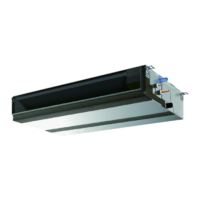
8. Duct work
• In connecting duct, insert canvas duct between unit and duct.
• Use incombustible material for duct parts.
• Provide full insulation to inlet duct flange and outlet duct to prevent condensation.
• Be sure to change the position of air filter to the position where it can be serviced.
[Fig. 8.0.1] (P.5)
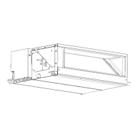
When the duct is connected to the inlet at the bottom of the unit, the sound
pressure level will be greater by approximately 10 dB than when the duct is
connected to the inlet at the back of the unit.
For this reason, it is recommended to connect the duct to the back inlet.
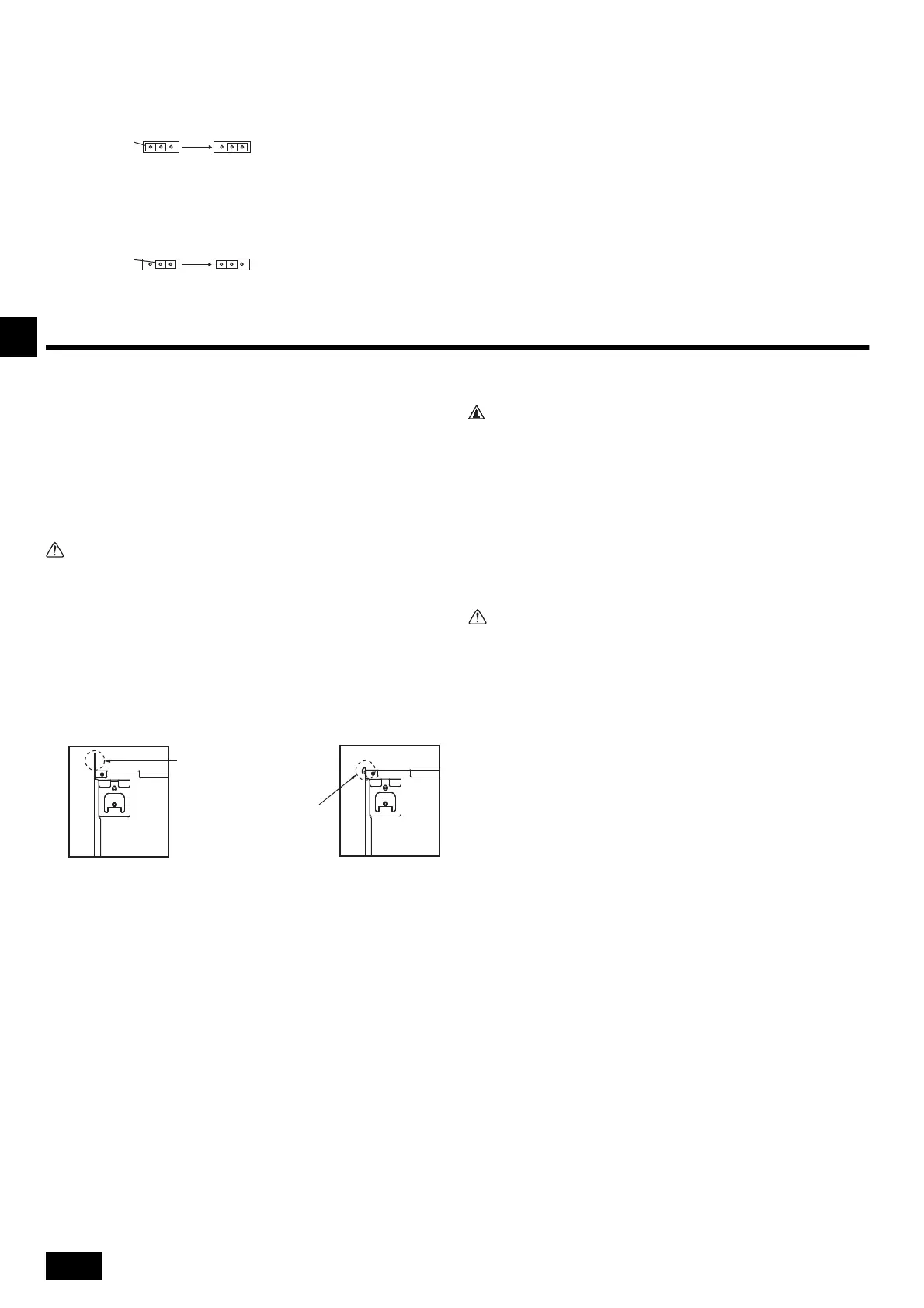
When using the inlet at the bottom of the unit, offset the position of the inlet on
the indoor unit relative to the inlet on the ceiling as shown in Figures <A> and
<B> to minimize noise.
[Fig. 8.0.2] (P.5)
1. Remove air filter. (First remove filter lock screw.)
2. Remove the bottom plate.
3. Fit the bottom plate to the rear of the body. [Fig. 8.0.3] (P.5)
(Position of lug-holes on the plate are different from those for rear inlet.)
4. Fit filter to the underside of the body.
(Be careful of which side of the filter to fit.) [Fig. 8.0.4] (P.5)
[Fig. 8.0.4] (P.5)
If one or more rooms are connected to the unit using a duct system, make
sure:
• Install the unit in a space with at least a minimum floor area defined in the
installation manual for the outdoor unit.
• no auxiliary devices, which may be a potential ignition source, are
installed in the duct work;
• only auxiliary devices approved by the manufacturer are used in the duct
work;
• an air inlet or outlet is connected directly with a room by ducting. Do NOT
use spaces such as a false ceiling as a duct for the air inlet or outlet.
• Do NOT install operating ignition sources (example: open flames, an oper-
ating gas appliance or an operating electric heater) in the duct work.
• Inlet duct of 850 mm or more should be constructed.
To connect the air conditioner main body and the duct for potential
equalization.
• To reduce the risk of injury from metal sheet edges, wear protective gloves.
• To connect the air conditioner main body and the duct for potential
equalization.
• The noise from the intake will increase dramatically if intake is fitted
directly beneath the main body. Intake should therefore be installed as far
away from the main body as possible.
Particular care is required when using it with bottom inlet specifications.
• Install sufficient thermal insulation to prevent condensation forming on
outlet duct flanges and outlet ducts.
• Keep the distance between the inlet grille and the fan over 850 mm. If it is
less than 850 mm, install a safety guard not to touch the fan.
• To avoid electrical noise interference, do not run transmission lines at the
bottom of the unit.
Connector
SWE
OFF ON OFF ON
SWE
<OFF> <ON>
Connector
SWE
OFF ON OFF ON
SWE
<ON> <OFF>
A Insert pump's end 2 to 4 cm.
B Remove the water supply port.
C About 2500 cc
D Water
E Filling port
F Screw
<Indoor controller board>
<A> In case of rear inlet
<B> In case of bottom inlet
A Duct B Air inlet
C Access door D Canvas duct
E Ceiling surface F Air outlet
G Leave distance enough to prevent
short cycle
H Min. 200 mm
A Filter B Bottom plate
When the plate is attached on
the rear side, it exceeds the
height of the rear body panel.
Replicate the plate along
the slit when there is not
enough room above for the
entire unit.
C Nail for the bottom inlet D Nail for the rear inlet
Warning:
01_KJ79P971H02_en.book 12 ページ 2022年7月5日 火曜日 午前11時38分
 Loading...