13
en
9. Electrical wiring
Precautions on electrical wiring
Electrical work should be done by qualified electrical engineers in accordance
with “Engineering Standards For Electrical Installation” and supplied
installation manuals. Special circuits should also be used. If the power circuit
lacks capacity or has an installation failure, it may cause a risk of electric
shock
or fire.
1. Be sure to install an earth leakage breaker to the power.
2. Install the unit to prevent that any of the control circuit cables (remote controller,
transmission cables) is brought in direct contact with the power cable outside the
unit.
3. Ensure that there is no slack on all wire connections.
4. Some cables (power, remote controller, transmission cables) above the ceiling
may be bitten by mouses. Use as many metal pipes as possible to insert the
cables into them for protection.
5. Never connect the power cable to leads for the transmission cables. Otherwise
the cables would be broken.
6. Be sure to connect control cables to the indoor unit, remote controller, and the
outdoor unit.
7. Put the unit to the ground on the outdoor unit side.
8. Select control cables from the conditions given in page 13.
• Be sure to put the unit to the ground on the outdoor unit side. Do not
connect the earth cable to any gas pipe, water pipe, lightening rod, or
telephone earth cable. Incomplete grounding may cause a risk of electric
shock.
• If the supply cord is damaged, it must be replaced by the manufacturer, its
service agent or similarly qualified persons in order to avoid a hazard.
9.1. Power supply wiring
• Use dedicated power supplies for the outdoor unit and indoor unit.
• Bear in mind ambient conditions (ambient temperature, direct sunlight, rain water, etc.) when proceeding with the wiring and connections.
• The wire size is the minimum value for metal conduit wiring. If the voltage drops, use a wire that is one rank thicker in diameter. Make sure the power-supply voltage does
not drop more than 10%.
• Specific wiring requirements should adhere to the wiring regulations of the region.
• Power supply cords of appliances shall not be lighter than design 60245 IEC 57, 60227 IEC 57, 60245 IEC 53 or 60227 IEC 53.
• A switch with at least 3 mm contact separation in each pole shall be provided by the Air conditioner installation.
[Fig. 9.1.1] (P.5)
Apply to IEC61000-3-3 about Max. Permissive System Impedance.
*1 The Ground-fault interrupter should support Inverter circuit.
The Ground-fault interrupter should combine using of local switch or wiring breaker.
*2 Please take the larger of F1 or F2 as the value for F0.
F1 = Total operating maximum current of the indoor units 1.2
F2 = {V1 (Quantity of Type1)/C} + {V1 (Quantity of Type2)/C} + {V1 (Quantity of Type3)/C} + {V1 (Quantity of Others)/C}
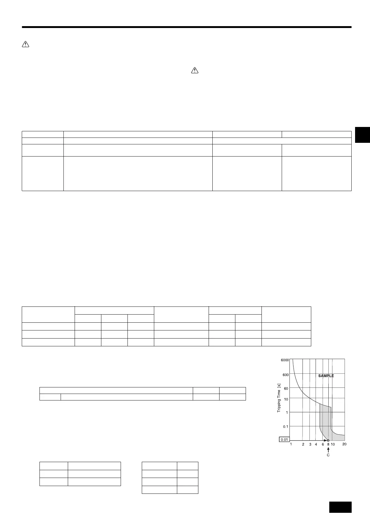
C : Multiple of tripping current at tripping time 0.01s
Please pick up “C” from the tripping characteristic of the breaker.
<Example of “F2” calculation>
*Condition PEFY-VMA 3, C = 8 (refer to right sample chart)
F2 = 18.6 3/8
= 6.975
16 A breaker (Tripping current = 8 16 A at 0.01s)
*3 Current sensitivity is calculated using the following formula.
G1 = (V2 Quantity of Type1) + (V3 Wire length [km])
Transmission cable specifications
*1 Connected with simple remote controller.
Transmission cables ME Remote controller cables MA Remote controller cables
Type of cable Shielding wire (2-core) CVVS, CPEVS or MVVS Sheathed 2-core cable (unshielded) CVV
Cable diameter More than 1.25 mm
2
0.3 ~ 1.25 mm
2
(0.75 ~ 1.25 mm
2
)*1
0.3 ~ 1.25 mm
2
(0.75 ~ 1.25 mm
2
)*1
Remarks
Max length: 200 m
Maximum length of transmission lines for centralized control and indoor/
outdoor transmission lines (Maximum length via indoor units): 500 m MAX
The maximum length of the wiring between power supply unit for
transmission lines (on the transmission lines for centralized control) and
each outdoor unit and system controller is 200 m.
When 10 m is exceeded, use
cables with the same specification
as transmission cables.
Max length: 200 m
CVVS, MVVS: PVC insulated PVC jacketed shielded control cable
CPEVS: PE insulated PVC jacketed shielded communication cable
CVV: PVC insulated PVC sheathed control cable
A Ground-fault interrupter
B Local switch/Wiring breaker
C Indoor unit
D Pull box
Total operating current of
the Indoor unit
Minimum wire thickness (mm
2
)
Ground-fault interrupter
*1
Local switch (A)
Breaker for wiring (A)
(Non-fuse breaker)
Main cable Branch Ground Capacity Fuse
F0 = 16 A or less
*2
1.5 1.5 1.5 20 A current sensitivity
*3
16 16 20
F0 = 25 A or less
*2
2.5 2.5 2.5 30 A current sensitivity
*3
25 25 30
F0 = 32 A or less
*2
4.0 4.0 4.0 40 A current sensitivity
*3
32 32 40
Indoor unit V1 V2
Type1 PEFY-VMA 18.6 3.0
G1 Current sensitivity Wire thickness V3
30 or less 30 mA 0.1 sec or less 1.5 mm
2
48
100 or less 100 mA 0.1 sec or less 2.5 mm
2
56
4.0 mm
2
66
Rated Tripping current (x)
Sample chart
01_KJ79P971H02_en.book 13 ページ 2022年7月5日 火曜日 午前11時38分
 Loading...