13
GB
5. After wiring is complete, make sure again that there is no slack on the connec-
tions, and attach the cover onto the terminal box in the reverse order of
removal.
Notes:
• Do not pinch the cables or wires when attaching the terminal box cover.
Doing so may cause a risk of disconnection.
• When accommodating the terminal box, make sure that the connectors on
the box side are not removed. If removed, it cannot operate normally.
9.4. External I/O specifications
1. Wiring should be covered by insulation tube with supplementary insulation.
2. Use relays or switches with IEC or equivalent standard.
3. The electric strength between accessible parts and control circuit should
have 2750 V or more.
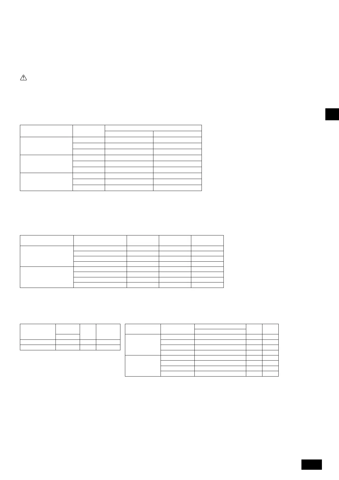
9.5. Selecting the airflow mode and external static pressure
This indoor unit supports two types of airflow modes and four external static pressure settings. The fan speed and the corresponding airflow rate for each mode vary with
models as shown in the table below.
Notes:
• When the airflow mode and the static pressure setting were set from the remote controller, the actual setting and the switch setting on the control board may
not match because the latest setting from the remote controller overrides the previous setting. To check the latest airflow mode and static pressure setting,
check them on the remote controller, not on the switch.
• If the static pressure setting for the duct is lower than that for the unit, the fan of the unit may repeat start/stop, and the outdoor unit may remain in a stopped
state. Match the static pressure settings for the unit to that for the duct.
To set the airflow mode and the static pressure setting with the switches on the control board
To set the airflow mode and the static pressure setting from the function selection screen on the remote controller (Some remote controllers do not support
the function selection function. Refer to the Instruction Book of a given remote controller.)
Follow the instructions below and the instructions detailed in the remote controller manual for how to set the switches.
1. Set the function setting No. 32 (Switch setting/Function selection) to “2”.
2. Set the function setting No. 115 to appropriate values, according to the airflow mode and the static pressure setting.
9.6. Setting addresses
(Be sure to operate with the main power turned OFF.)
[Fig. 9.5.1] (P.6)
• There are two types of rotary switch setting available: setting addresses 1 to 9
and over 10, and setting branch numbers.
• The rotary switches are all set to “0” when shipped from the factory. These
switches can be used to set unit addresses and branch numbers at will.
• The determination of indoor unit addresses varies with the system at site. Set
them referring to the Data Book.
Model Fan speed
Airflow rate [m
3
/min]
Normal-airflow rate mode High-airflow rate mode
PEFY-P125VMHS-E-F
High 18 20
Medium 15.5 18
Low 14 15.5
PEFY-P200VMHS-E-F
High 28 32
Medium 25 28
Low 22.5 25
PEFY-P250VMHS-E-F
High 35 40
Medium 31 35
Low 28 31
Airflow mode External static pressure SW21-1 SW21-2 SW21-5
Set the switches on the control board (SW21-1,
SW21-2, and SW21-5) as shown in the table at left.
Normal-airflow rate mode
100 Pa OFF OFF OFF
150 Pa ON OFF OFF
200 Pa OFF ON OFF
250 Pa ON ON OFF
High-airflow rate mode
100 Pa OFF OFF ON
150 Pa ON OFF ON
200 Pa OFF ON ON
250 Pa ON ON ON
Selection
Function
setting No.
Initial
Setting
Current
setting
Airflow mode
External static
pressure setting
Function setting No.
Initial
setting
Current
setting
[Important]
Be sure to write down
the settings for all
functions in the “Cur-
rent setting” row if any
of the initial settings
has been changed.
No. 115
No. 32
Normal-airflow rate
mode
100 Pa 1
Switch setting 1 ○ 150 Pa 2
Function selection 2 200 Pa 3 ○
250 Pa 4
High-airflow rate
mode
100 Pa 5
150 Pa 6
200 Pa 7
250 Pa 8
<Indoor controller board>
1 How to set addresses
Example: If Address is “3”, remain SW12 (for over 10) at “0”, and match SW11 (for 1 to 9)
with “3”.
2 How to set branch numbers SW14 (Series R2 only)
The branch number assigned to each indoor unit is the port number of the BC controller
to which the indoor unit is connected.
Leave it to “0” on the non-R2 series of units.
WT08819X02.book 13 ページ 2018年5月9日 水曜日 午後5時14分
 Loading...