10 11
TCH123
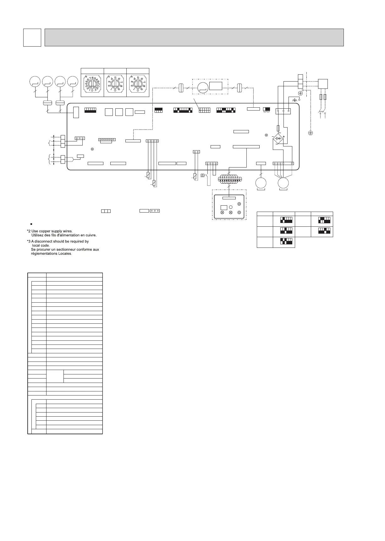
WIRING DIAGRAM6
<Fig.*1> SW2 (CAPACITY CODE)
MODELS
WL04
ON
OFF
123456
WL12
ON
OFF
123456
WL06
ON
OFF
123456
WL08
ON
OFF
123456
WL15
ON
OFF
123456
SW2 MODELS SW2
[LEGEND]
SYMBOL
I.B
NAME
INDOOR CONTROLLER BOARD
REMOTE SWITCHCN32
EXTERNAL HEATERCN24
CENTRALLY CONTROLCN51
REMOTE INDICATIONCN52
IT TERMINALCN105
FUSE(T6.3AL 250V)F1
POWER SUPPLY (I.B)LED1
MODE SELECTIONSW1
CAPACITY CODESW2
MODE SELECTIONSW3
ADDRESS SETTING 1s DIGITSW11
ADDRESS SETTING 10s DIGITSW12
BRANCH No.SW14
CEILING HEIGHT SELECTORSW21
PAIR NO. SETTINGSW22
DRAIN PUMP (TEST MODE)SWE
DP DRAIN PUMP
MF FAN MOTOR
MV VANE MOTOR
FS FLOAT SWITCH
TH21 ROOM TEMP. THERMISTOR
TH22
PIPE TEMP. THERMISTOR (INLET)
TH23
W.B
OPTION PART
PIPE TEMP. THERMISTOR (OUTLET)
WIRELESS REMOTE CONTROLLER BOARD
BUZZERBZ
OPERATION (GREEN)
LED1
STAND BY (ORANGE)
LED2
RECEIVING UNIT
RU
EMERGENCY OPERATION(HEAT)
SW1
EMERGENCY OPERATION(COOL)
SW2
MT i-see Sensor MOTOR
TB2 TERMINAL POWER SUPPLY
TRANSMISSIONTB5
MA-REMOTE CONTROLLER
TB15
BLOCK
POWER SUPPLY (MA-REMOTE CONTROLLER)
LED2
GRILLE
MV
5
M
MV
5
10
TO OUTDOOR UNIT
BC CONTROLLER
M-NET REMOTE
TO MA-REMOTE
TB5
S
M2
TB15
2
2
3 1
1
1 5 1 5
CN2A
LED2
CN52
1
14
t°
TH21
1 4
1
6
1 3
9
9
9
CNB
RU
BZ
SW2
SW1LED2LED1
1
1
W.B
10
3
1 3 7 4 1
DP
MS
CNP CNMF
3~
MF
MS
3~
FS
CN4F
CNSBCNSA
1 2
1
1
4 1
135
5
9
CN20
1
2
CN24
CN90
CN105
CN4Z
LED1
CND
POWER SUPPLY
~/N 208/230V 60Hz
BK
RD
BU
TB2
TO NEXT
INDOOR
UNIT
PULL
BOX
*3
FUSE(15A)
L2
L1
*2
t°
TH22
t°
TH23
5
1 8
CN51
CN5Y
CN44
CN3M
CN8A
1
M1
CONTROLLER
8.7-13V DC
CONTROLLER
24-30V DC
10
20
CNV
19
SW21
SW14
Detail of SW11, SW12 and SW14
BRANCH No.
Switches in the picture show “0”.
SW12
10s DIGIT
SW11
1s DIGIT
SW14
BRANCH
No.
10s
DIGIT
1s
DIGIT
SW12 SW11
CN32
ON
OFF
2 1
13
1 234
SW22 SW1
5 5
4 4
i-see
i-see Sensor
CORNER PANEL
(OPTION PART)
Sensor
MT
M
SW2
See Fig.*1
SW3
SWE
ON
F1
OFF
ON
OFF
ON
OFF
ON
OFF
ON
OFF
1 234 1 2 3 45 6 1 2345 67 89 0 1 2345 67 89 056
M
MV
5
M
MV
5
M
I.B
Notes:
1.At servicing for outdoor unit,always follow the wiring diagram of outdoor unit.
2.In case of using MA-Remote controller, please connect to TB15. (Remote controller wire is non-polar.)
3.In case of using ME-Remote controller, please connect to TB5. (Transmission line is non-polar.)
4.Symbol [S]of TB5 is the shield wire connection.
5.Symbols used in wiring diagram above are, : terminal block, : connector.
6.The setting of the SW2 differs in the capacity. For the detail, refer to the Fig.*1.
7.Make sure to turn off the indoor and the outdoor units before replacing indoor controller board.
8. is the switch position.
 Loading...