1918
TCH123
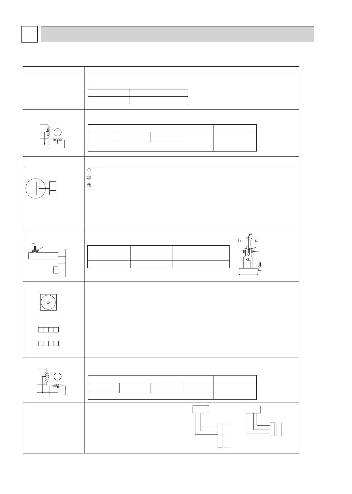
9-1. HOW TO CHECK THE PARTS
Parts name Checkpoints
Disconnect the connector then measure the resistance with a multimeter.
(At the ambient temperature 50°F ~ 86°F)
Measure the resistance between the terminals with a multimeter.
(At the ambient temperature 68
°F ~ 86°F)
Vane motor (MV)
Refer to “9-2-1. Thermistor Characteristic Graph”.
Thermistor (TH21)
(Room temperature detection)
Thermistor (TH22)
(Pipe temperature detection/inlet)
Thermistor (TH23)
(Pipe temperature detection/outlet)
Normal
4.3 to 9.6 k
Ω
Abnormal
Open or short
Orange
Red
White
Blue
Yellow
M
Refer to “9-1-4. DC Fan motor (fan motor/indoor controller board)”.
Fan motor (MF)
Drain float switch (FS)
2
1
Moving part
4
3
Measure the resistance between the terminals with a multimeter.
State of moving part
Abnormal
DOWN Other than open
UP
Normal
Open
Short Other than short
i-see Sensor *
i-see Sensor motor *
Orange
Red
White
Blue
Yellow
M
Measure the resistance between the terminals with a multimeter.
(At the ambient temperature 68°F ~ 86°F)
Drain pump (DP)
1
2
3
Red
Purple
Black
Check if the drain float switch works properly.
Check if the drain pump works and drains water properly in cooling operation.
If no water drains, confirm that the check code 2502 will not be displayed 10 minutes after the
operation starts.
Note: The drain pump for this model is driven by the internal DC motor, so it is not possible to
measure the resistance between the terminals.
Normal
Red–Black: Input 13 VDC → The fan starts to rotate.
Purple–Black: Abnormal (check code 2502) if it outputs 0–13 V square wave (5 pulses/rotation), and
the number of rotation is not normal.
1 2 3
4
1 2 3
4
Black
Black
Black
Black
Turn the power ON while the i-see Sensor connector is connected to the CN4Z on indoor controller
board. A communication between the indoor controller board and i-see Sensor board is made to
detect the connection.
Normal: When the operation starts, the motor for i-see Sensor is driven to rotate the i-see Sensor.
Abnormal: The motor for i-see Sensor is not driven when the operation starts.
Note: The voltage between the terminals cannot be measured accurately since it is pulse output.
250
Ω ± 7%
* i-see Sensor is available with optional “i-see Sensor corner panel” (SLP-18FAEU).
AbnormalNormal
Red–Yellow Red–Blue Red–Orange
Open or short
Red–White
300
Ω ± 7%
AbnormalNormal
Red–Yellow Red–Blue Red–Orange
Open or short
Red–White
PS1
6 5 4 3 2 1
GND(RED)
Vout(Brown)
Vcc(DC5V)(Orange)
Connector
CNSA
(White)
PS2
3 2 1
GND(Blue)
Vout(White)
Vcc(DC5V)(Yellow)
Connector
CNSB
(Black)
Pressure sensor
(Optional parts)
▪ Pressure sensor (inner water) PS1
▪ Pressure sensor (outlet water) PS2
1. Check that the pressure sensor is connected.
2. Check the pressure sensor wiring for breakage.
Pressure 0-1.0 MPa [145 psi] Vout 0.5-4.5 V
0.392 V/ 0.098 MPa [14 psi]
Pressure [MPa] = 0.25 × Vout [V] - 0.125
Pressure [psi] = (0.25 × Vout [V] - 0.125) × 145
TROUBLESHOOTING
9
 Loading...