19
TCH123
18
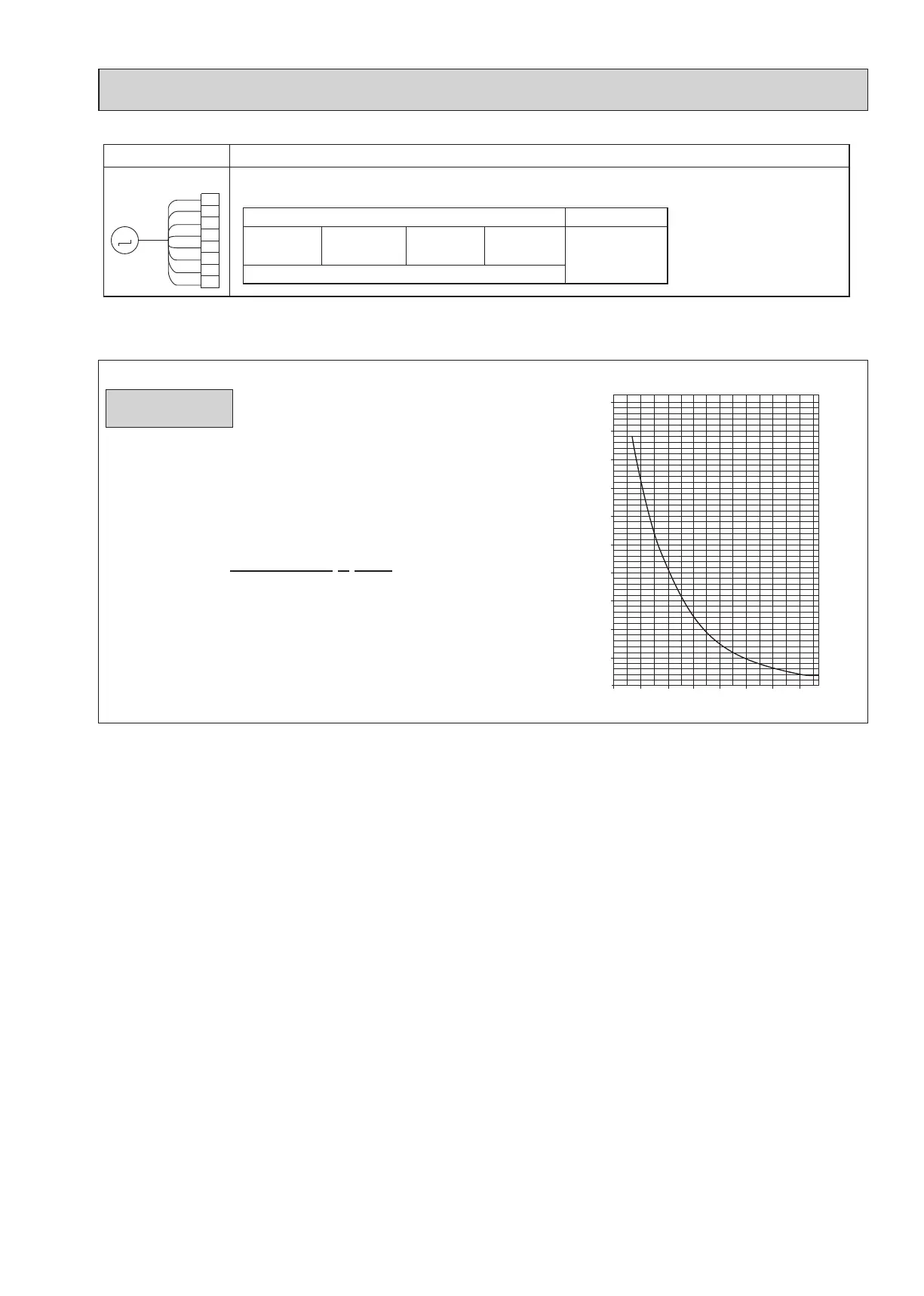
9-1-1. Thermistor Characteristic Graph
Parts name Checkpoints
Disconnect the connector then measure the resistance between terminals with a multimeter.
Refer to "8-1-2. Flow control valve".
Flow control valve
(FCV)
Normal
55 Ω ± 5.6 Ω (at 77°F)
1-5
Purple-Brown
2-5
Orange-Brown
3-5
Blue-Brown
4-5
Green-Brown
1
2
3
4
5
6
FCV
Yellow
Orange
Red
Green
Blue
Purple
CN8A
M
7
8
White
Gray
Abnormal
Open or short
(Optional parts)
thermistor (TH21)
(Room temperature detection)
thermistor (TH22)
(Pipe temperature detection/ inlet)
thermistor (TH23)
(Pipe temperature detection/ outlet)
Thermistor R0=15 k" ± 3%
Fixed number of B=3480 ± 2%
Rt=15exp { 3480( ) }
30°F 15.8kΩ
50°F 9.6kΩ
70°F 6.0kΩ
80°F 4.8kΩ
90°F 3.9kΩ
100°F 3.2kΩ
Thermistor for
lower temperature
1
273+(t-32)/1.8
1
273
0
10
20
30
40
50
0-20 20 40 60 80 100 120
< Thermistor for lower temperature >
Temperature (°F)
Resistance (kΩ)
 Loading...