En-11
Refertotheproceduresindicatedintheinstallationmanualoftheoutdoorunit.
• Connectaninterfacetotheindoorcontrolboardofanairconditionerwithaconnectingcable.
• Cuttingorextendingtheconnectingcableoftheinterfaceresultsindefectsinconnecting.Donotbundletheconnectingcabletogetherwithpowersupply
cord,indoor/outdoorconnectingwire,and/orgroundwire.Keepasmuchdistanceaspossiblebetweentheconnectingcableandthosewires.
• Thethinpartoftheconnectingcableshouldbestoredandplacedwherecustomerscannottouchit.
6. PUMPING DOWN
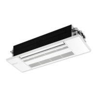
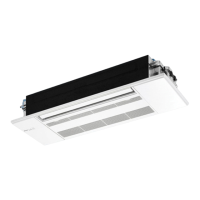
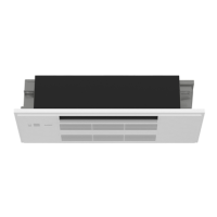
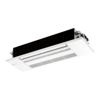
7. CONNECTING AN INTERFACE (OPTION) TO THE AIR CONDITIONER
When pumping down the refrigerant, stop the compressor before disconnecting
the refrigerant pipes. The compressor may burst if air etc. get into it.
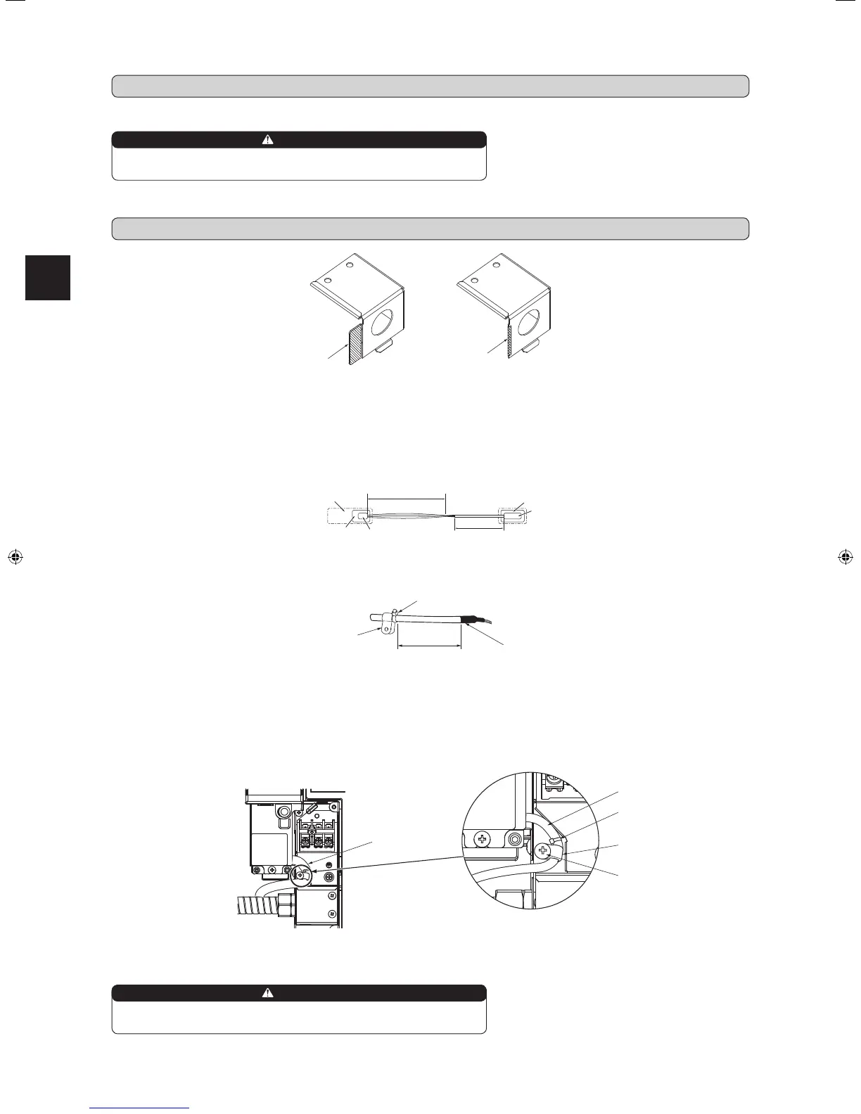
1)Fixthecabletietotheconnectingcableat3-15/16in.(100mm)fromtheedgeoftheinsulationcoatingpart.Attachthemountingcordclamp(medium)to
theinterfacesideofthecabletie.
2)Removethegrille.(Ifthegrillehasbeenalreadyinstalled)
3)Removetheelectricalcover(1),(2).
Referto2-4.CONNECTINGWIRESFORINDOORUNIT.
4)Slideouttheindoorcontrolboard,andconnecttheconnectingcabletoCN105and/orCN24ontheindoorcontrolboard.
5)Removethescrewshowninthephotoblow.Routetheconnectingcableaccordingtothephotobelow.Fixthemountingcordclamp(medium),whichhas
attachedtotheconnectingcable,withthescrew.
6)Reinstalltheindoorcontrolboardandtheelectricalcover(1),(2).
7)Reinstallthegrille.
Mountingcordclamp(medium)
Cabletie
3-15/16in.
(100mm)
Insulationcoatingpart
Mountingcordclamp
(medium)
Connecting
cable
Cabletie
Thinpartoftheconnectingcable.Placethispart
wherecustomerscannottouchit.
Roomairconditioner
Indoorcontrolboard
CN105forinterface
CN24forconnectorcable
Thickpartoftheconnectingcable
Mainbodyofaninterface
Connector
Fix the connecting cable at the prescribed position securely.
Incorrect installation may cause electric shock, re, and/ or malfunction.
WARNING
WARNING
(A)
Q
Ifyouattachthisoptionalparttothemodel,fold(A)afewtimesandcutit.
Covethecutpartwithprotectivetape
Q
.
Connectingcable
Screw
RG79Y948H01_en.indd 11 2018/01/23 11:41:57
 Loading...