17
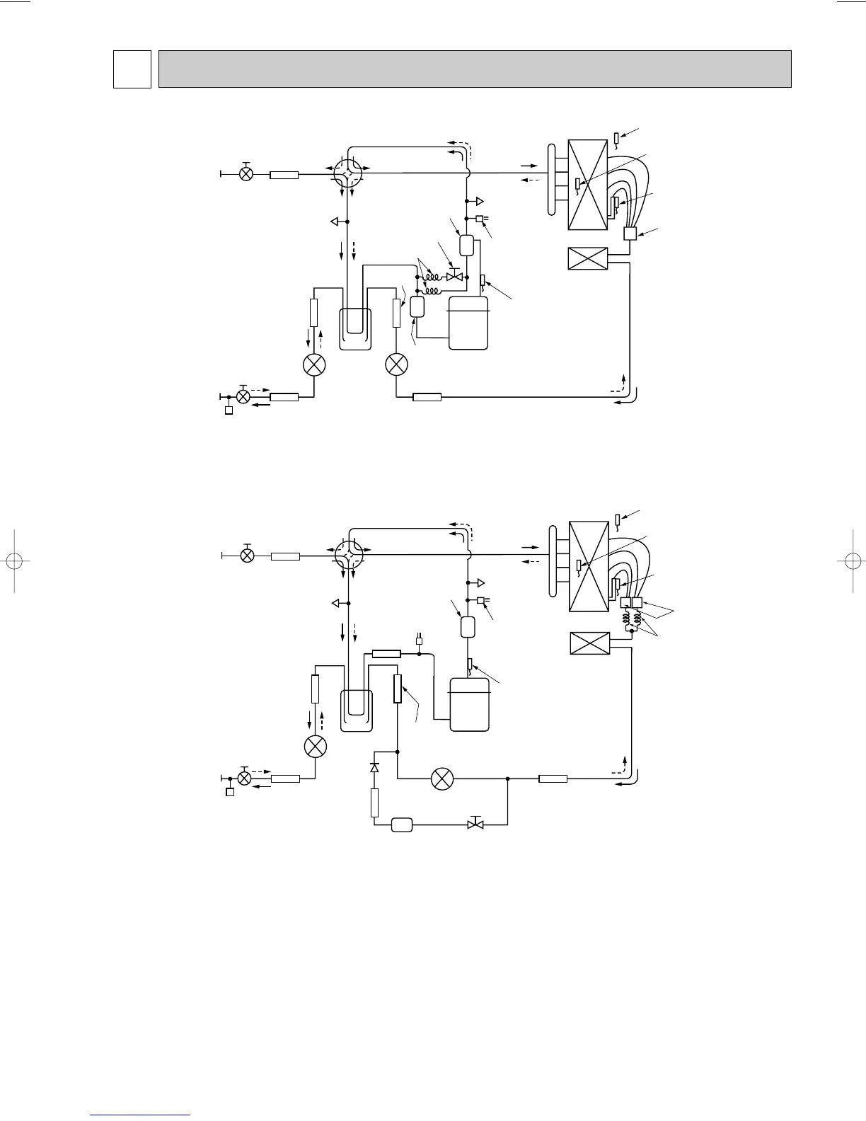
9 REFRIGERANT SYSTEM DIAGRAM
PUHZ-RP4VHA
PUHZ-RP5VHA
PUHZ-RP6VHA
Distributor
Thermistor TH7
(Outdoor outside temperature)
Heat exchanger
Refrigerant GAS pipe
connection(5/8F)
Refrigerant LIQUID pipe
connection(3/8F)
Stop valve
(with service port)
Strainer(#100)
Power
receiver
Electronic expansion valve B
Electronic expansion valve A
Strainer(#100)
Strainer
(#100)
Strainer
(#100)
Thermistor TH6
(Outdoor condenser/evaporator
temperature)
Thermistor TH3
(Outdoor liquid pipe temperature)
Service port
(Low pressure)
Service port
(High pressure)
High pressure
protect switch
Bypass valve
Replace filter
Thermistor TH4
(Outdoor discharge
pipe temperature)
Compressor
Strainer(#50)
4-way valve
Capillary tube
(O.D.4.0OI.D.3.0OL200)O2pcs
Strainer
(#100)
Strainer
(#100)
Low pressure
protect switch
Muffler
Ball valve
Restrictor
valve
PUHZ-RP3VHA
Distributor
Thermistor TH7
(Outdoor outside temperature)
Heat exchanger
Refrigerant GAS pipe
connection(5/8F)
Refrigerant LIQUID pipe
connection(3/8F)
Stop valve
(with service port)
Strainer(#100)
Power
receiver
Electronic expansion valve B
Electronic expansion valve A
Strainer(#100)
Strainer
(#100)
Strainer
(#100)
Thermistor TH6
(Outdoor condenser/evaporator
temperature)
Thermistor TH3
(Outdoor liquid pipe temperature)
Service port
(Low pressure)
Service port
(High pressure)
High pressure
protect switch
Bypass valve
Oil separator
Thermistor TH4
(Outdoor discharge
pipe temperature)
Muffler
Strainer(#50)
4-way valve
Compressor
Ball valve
Capillary tube
OC294--1.qxp 03.6.9 7:36 PM Page 17
 Loading...