31
Select Calibration Table (after Light Source Unit replacement)
1. In the Customer’s Video Settings Menu select COLOR TEMP: HIGH
2. Enter the Service Menu <MENU-<2-4-5-7>.
3. Use the <VIDEO> button to select the adjustment, “61.BCMH” and note the data value (0, 1, 2, 3 or 4).
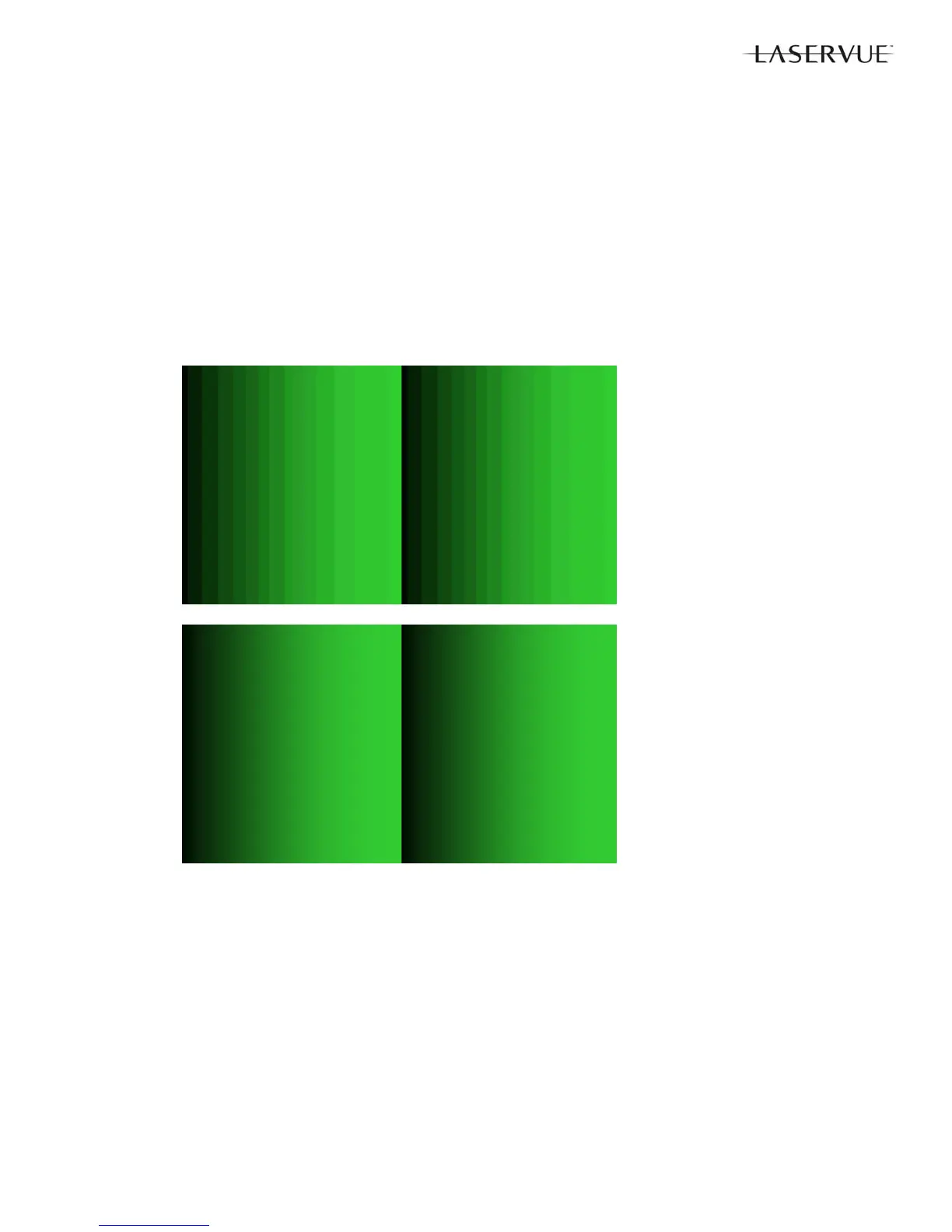
4. Select the Green Double Ramp Pattern by pressing PLAY <
> twice, then FAST FORWARD <> or
REWIND <
> until the pattern below appears.
5. Check the pattern for smoothness of graduation from dark to light and for the presence any vertical contour
lines.
6. Use the DIRECTION <
> buttons to alternately change the Data Value of “61.BCMH” to 0, 1, 2, 3 or 4.
As necessary, press PLAY <
> once to observe the Service Menu on screen display and press PLAY <>
twice to return to the pattern.
7. Select the data value 0, 1, 2, 3 or 4 that gives the best results. No higher data value should be used.
8. Press <ENTER> to save the adjustment.
Before
Adjustment
After
Adjustment
Manual Geometry Alignment
1. Activate the Service Mode <MENU><2-4-5-7>. From the Service Menu, press the <0> button. The Data Trans-
fer & Geometry Menu will appear.
2. Use the <
> buttons to select “MANUAL GEOMETRY ALIGNMENT” and press <ENTER>.
3. The Manual Geometry Alignment Pattern will appear. See below.
4. Prepare for the alignment by resetting the geometry data. Press <1> then <ENTER>. The previous menu will be
displayed. Select “MANUAL GEOMETRY ALIGNMENT” and press <ENTER> again to proceed.
Note 1: Upon entering the Manual Geometry Alignment Mode the first time, the geometry may appear distorted
because all factory geometry correction is automatically disabled. Press <EXIT> to quit and re-enable
the factory geometry correction. Pressing <1> <ENTER> and <EXIT> will cause the TV to operate with
out factory geometry correction (distortion will be present).
Note 2: At any time the original factory geometry data can be restored from backup:
From the Data Transfer & Geometry Menu <MENU><2-4-5-7><0>, select “RESTORE GEOMETRY
DATA FROM BACKUP” <ENTER>.
 Loading...