12
7 Press SET button (Fixing of the upper
limit position)
The upper limit position is fixed and the setting position is
displayed for two seconds. Then proceed to lower limit position
selection display.
[EXAMPLE]
“
” (lights for two seconds)
È
“
” (shows current setting)
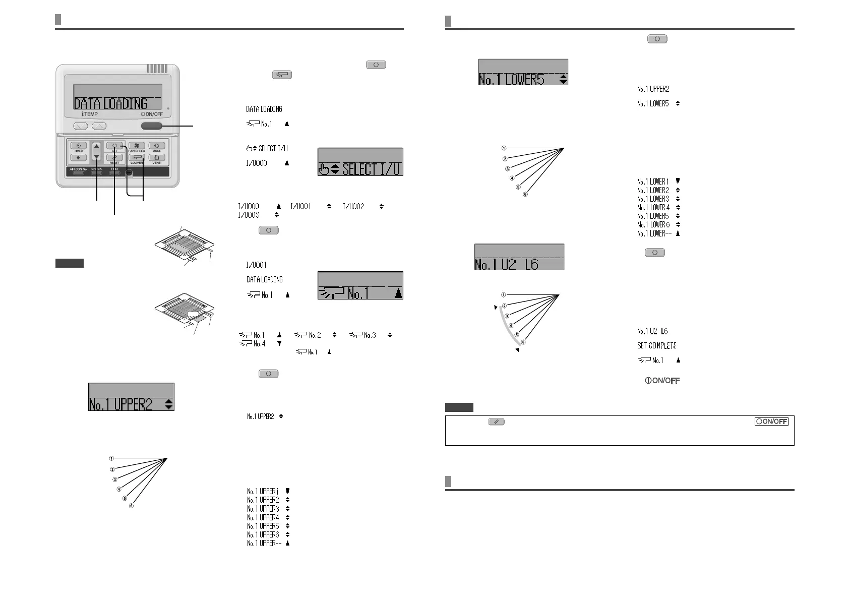
8 Press Ÿ or ź button (Selection of lower limit
position)
Select the lower limit position of louver.
“position 1” is the most horizontal, and “position 6” is the most
downwards.
“position
--
” is to return to the factory setting. If you need to change
the setting to the factory setting, use “position
--
”.
“
” (the most horizontal)
⇔ “
”
⇔ “
”
⇔ “
”
⇔ “
”
⇔ “
” (the most downwards)
⇔ “
” (return to the position of shipment)
9 Press SET button (Fixing of the lower limit
position)
The upper limit position and lower limit position are xed, the set
positions lights for two seconds, and then the setting is completed.
• After the setting is completed, the louver which was set
moves from the original position to the lower limit position,
and goes back to the original position again. (This operation
is not performed if the indoor unit and/or indoor unit fan is in
operation.)
[Example]
“
” (lights for two seconds)
È
“
”
È
“
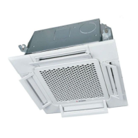
10
Press button.
Louver adjusting mode ends and returns to the original display.
HOW TO SET THE AIR FLOW DIRECTION
< WIRED REMOTE CONTROL (RC-E series) >
NOTICE
(downwards)
(horizontal)
the position of the louver
[EXAMPLE] For Upper position 2, Lower position 6
Lower
position
Movable
range
Upper
position
• When plural remote controllers are connected, louver position setting cannot be set by slave remote control.
• If you press RESET button during settings, the display will return to previous display. If you press
button during settings, the mode will end and the original display will return, and the settings that have not been
completed will become invalid.
Note : If the upper limit position number and the lower limit
position number are set to the same position, the louver is
xed at that position. And auto swing does not function.
AIROUTLET SELECTION
(IN CASE OF FDFW)
It is possible to switch between the combination of upper and lower air outlets and upper air outlet.
Not operable while the air conditioner is ON.
When the upper air flow is selected, UPPER AIR FLOW LED on the unit display will light green only under run.
1. Stop the air conditioner.
2. Set the upper land lower limit position of the louver No.1 from the wired remote control.
For the method of changing the setting, refer to HOW TO SET THE AIR FLOW DIRECTION on the left side.
1
In case of selecting to upper air flow.
Set the upper and lower limit position to UPPER 2 and LOWER 2. (No.1 UPPER 2 / LOWER 2)
2
In case of selecting to upper and lower air flow.
Set the upper and lower limit position to UPPER 5 and LOWER 5. (No.1 UPPER 5 / LOWER 5)
1
Stop the air conditioner and press SET
button and
LOUVER button simultaneously
for three seconds or more.
The following is displayed if the number of the indoor units
connected to the remote control is one. Go to step
4.
“
”
È
“
”
The following is displayed if the number of the indoor units
connected to the remote control are more than one
“
”
È
“
”
2 Press Ÿ or ź button.(selection of indoor unit)
Select the indoor unit of which the louver is set.
[EXAMPLE]
“ ”⇔“ ”⇔“ ”⇔
“ ”
3 Press
SET button. (determination of
indoor unit)
Selected indoor unit is xed.
[EXAMPLE]
“ ” (lights for two seconds)
È
“
”
È
“
”
4 Press Ÿ or ź button. (selection of louver No.)
Select the louver No. to be set according to the left gure.
[EXAMPLE]
“ ” ⇔ “ ” ⇔ “ ” ⇔
“ ”
Note : For FDE, select “
”. Other louver No. settings
have no effect.
5 Press
SET button. (Determination of
louver No.)
The louver No. to be set is con rmed and the display shows the
upper limit of the movable range.
[EXAMPLE] If No.1 louver is selected,
“
” ĸcurrent upper limit position
6 Press Ÿ or ź button. (selection of upper limit
position)
Select the upper limit of louver movable range.
“position 1” is the most horizontal, and “position 6” is the most
downwards.
“position
--
” is to return to the factory setting. If you need to
change the setting to the factory setting, use “position
--
”.
“
” (The most horizontal)
⇔ “
”
⇔ “
”
⇔ “
”
⇔ “
”
⇔ “
” (The most downward)
⇔ “
” (Return to the position of shipment)
2•4•6•8 1
10
3•5•7•9
HOW TO SET THE AIR FLOW DIRECTION
(IN CASE OF FDT, FDTC, FDE, FDK, FDFW) <WIRED REMOTE CONTROL (RC-E series) >
No. 4
No. 2
No. 1
No. 3
Control box
Piping side
Drain
hose side
Louver No.
[for FDT]
It is possible to change the movable range of the louver on the air outlet from the wired remote control. Once the top and bottom positions are set,
the louver will swing within the range between the top and the bottom positions when swing operation is chosen.
With Ceiling cassette −4 way − FDT and FDTC, it is also possible to apply different setting to each louver.
NOTICE
• For FDT and FDTC type, in case
the louver No. to be set is uncertain,
set any louver temporarily. The
louver will swing once when
the setting is completed and it is
possible to con rm the louver No.
and the position.
After that, choose the correct louver
No. and set the top and bottom
positions.
•
For FDE and FDK type, set louver
No. 1.
For FDFW type, set louver No. 2.
Other settings selected have no
effect.
downwards
(horizontal)
the position of the louver
No. 4
No. 2
No. 1
No. 3
Control box
Piping
side
Drain hose side
Louver No.
[for FDTC]
 Loading...