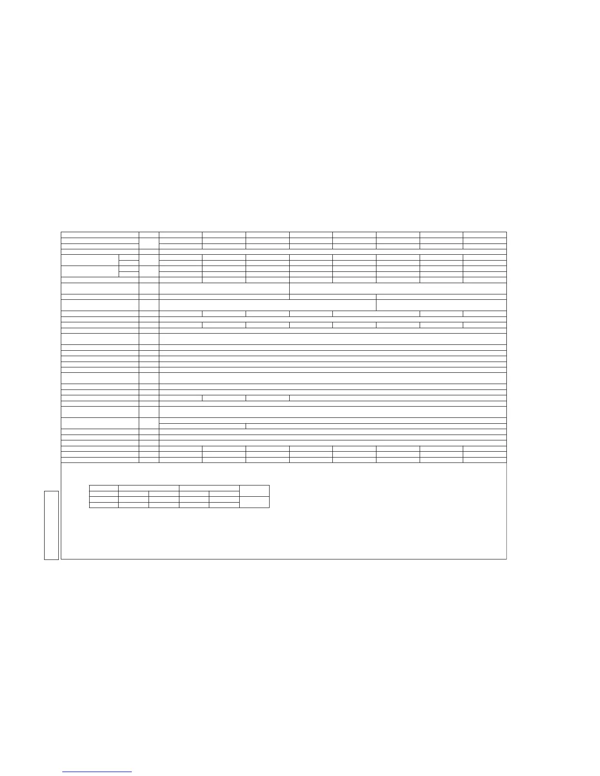
Notes (1) The data are measured at the following conditions.
Item
Indoor air temperature Outdoor air temperature
Standards
Adapted to RoHS directive
Operation DB WB DB WB
Cooling*1 19 ℃ 35 ℃ 24 ℃
ISO-T1
Heating*2 20 ℃ - 7 ℃ 6 ℃
ISO-T1 "UNITARY AIR-CONDITIONERS"
27 ℃
Models
Nominal cooling capacity*1
kW
Nominal heating capacity*2
Power source
Power consumption
Cool
kW
Heat
Running current
Cool
A
Heat
Sound Pressure Level dB(A)
Exterior dimensions
Height × Width × Depth
mm
Net weight kg
Refrigerant equipment
compressor type & Q'ty
Motor kW
Starting method
capacity control %
Crankcase heater W
Refrigerant equipment
Heat exchanger
Refrigerant control
Refrigerant
Quantity kg
Refrigerant oil l
Defrost control
Air handling equipment
fan type & Q'ty
Motor W
Starting method
Air flow(Standard) CMM
Shock & vibration absorber
safety equipment
Installation data
Refrigerant piping size
mm(in)
Connecting method
Drain
Insullation for piping
Accessories
Exterior dimensions
Electrical wiring
33.5 40.0 45.0 50.4 56.0 61.5 68.0
37.5 45.0 50.0 56.5 63.0 69.0 73.0
8.94 11.27 12.97 14.73 16.79 20.37 24.98
8.93 11.73 13.10 15.12 16.79 18.48 19.08
14.5/13.3
59/59 59.5/60 62.5/62.5 61.5/62 63/63.5 64.5/64 65/65
14.8/13.5 19.6/17.9 21.7/19.9 25.2/23.1 28.0/25.7 30.7/28.1 31.6/29.0
18.4/16.9 21.1/19.3 24.1/22.0 27.4/25.1 33.1/30.3 40.3/36.9
1690×1350×720 2048×1350×720
317 341 355
GTC5150NH48L×2 GTD5160NH48L×2
2.99×2 3.71×2 4.29×2 4.87×2 5.78×2 6.66×2 7.15×2
Direct line starting
19-130 15-114 13-112 11-100 10-113 11-110 10-108
33×2
Straight fin & inner grooved tubing
Electronic expansion valve
R410A
11.5
4.2(M-MA32R)
Microcomputer controlled De-Icer
Propeller fan × 2
386×2
Direct start
220/180 250/220 260/240 270/250
Compressor overheat protection / overcurrent protection / power transistor overheating
protection / abnormal high pressure protection
- - - - - - -
PCB003Z041 PCB003Z041 PCB003Z041 PCB003Z044 PCB003Z044 PCB003Z044 PCB003Z044
PCB003Z060 PCB003Z060 PCB003Z060 PCB003Z060 PCB003Z060 PCB003Z060 PCB003Z060
(2) This packaged air-conditioner is manufactured and tested in conformity with the following standard.
FDC335KXE6-K FDC400KXE6 FDC450KXE6 FDC504KXE6 FDC560KXE6 FDC560KXE6-K FDC615KXE6 FDC680KXE6
12-113
-
PCB003Z044
PCB003Z060
3 Phase 380-415V 50Hz/380V 60Hz
Rubber mount(for compressor)
Liquid line:φ12.7(1/2")
Gas line:φ28.58(11/8")
Gas line:Brazing / Liquid line:Flare
Hole for drain(φ20 × 6pcs , φ45 × 3pcs)
Necessary(both Liquid & Gas lines)
56.0
63.0
16.79
16.79
63/63.5
28.0/25.7
27.4/25.1
(3) Refrigerant piping size applicable to European installations are shown in parentheses.
Gas line:φ25.4(1")(φ28.58(11/8"))
 Loading...