MPI <6A1> -
Troubleshooting
13A-146
INSPECTION PROCEDURE FOR TROUBLE SYMPTOMS
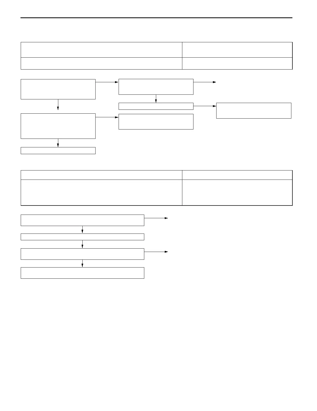
INSPECTION PROCEDURE 1
Communication with MUT-
II
is not possible.
(Communication with all systems is not possible.)
Probable cause
The cause is probably a defect in the power supply system (including earth) for the
diagnosis line.
D
Malfunction of the connector
D
Malfunction of the harness wire
OK
Replace the MUT-
II
.
OK
Check trouble symptom.
NG
Check the harness wire between the
power supply and diagnostic connector
(16-pin), and repair if necessary.
NG
Repair
NG
Check the following connectors:
LHD: C-141, C-132, C-63, C-66
RHD: C-14, C-62, C-66
Measure at the diagnostic connector
(16-pin) C-20.
D
Voltage between 16 and earth
OK:
Battery voltage
OK
Measure at the diagnostic connector
(16-pin) C-20.
D
Continuity between 4 and earth
D
Continuity between 5 and earth
OK:
Continuity
NG
Check the harness wire between the
diagnosticconnector(16-pin)andearth,
and repair if necessary.
INSPECTION PROCEDURE 2
MUT-
II
communication with engine-ECU is impossible.
Probable cause
One of the following causes may be suspected.
D
No power supply to engine-ECU.
D
Defective earth circuit of engine-ECU.
D
Defective engine-ECU.
D
Improper communication line between engine-ECU and MUT-
II
D
Malfunction of engine-ECU power supply circuit
D
Malfunction of engine-ECU
D
Open circuit between the engine-ECU and diagnosis
connector
OK
Check the engine-ECU power supply and earth circuit system.
(Refer to P.13A-170, INSPECTION PROCEDURE 26.)
NG
Check the harness wire between engine-ECU and diagnosis con-
nector.
NG
Repair
OK
Check trouble symptom.
Check the following connectors:
C-166, C-83, C-66, C-20
NG
Repair
 Loading...