HEAD OFFICE : MITSUBISHI DENKI BLDG MARUNOUTI TOKYO 100-8310
HIMEJI WORKS : 840, CHIYODA CHO, HIMEJI, JAPAN
4. Wiring
Caution:
Cut off all phases of power source before installing / removing or performing wiring work on
the expansion board in order to avoid electric shock or damage of product.
Note:
• Do not lay signal cable near to high voltage power cable or house them in the same
trunking duct. Effects of noise or surge induction may occur. Keep signal cables a safe
distance of more than 100 mm (3.94") from these power cables.
• Ground the shied wire or the shield of a shielded cable. Do not, however, ground at the
same point as high voltage lines.
• Never solder the end of any cables.
Make sure that the number of connected cables is not more than the unit has been
designed for.
• Never connect cables of a non permitted size.
• Fix cables so that any stress is not directly applied on the terminal block or the cable
connection area.
• The terminal tightening torque is 0.5 ~
0.6
N
"
m. Tighten securely to avoid malfunction.
• Do not use to the terminal.
4.1 Applicable cables
• Use AWG26 ~ 16 for connection with output equipment.
• The maximum tightening torque is 0.5 ~ 0.6 N•m.
• When using a different type of cable, defective contact at the terminal is possible. Use a crimp
terminal to achieve a good contact.
4.2 Wiring
4.2.1 Voltage Output Mode
*1 Connect a 0.1 ~ 0.47µF at 25V DC capacitor in position”*1” when there will be a lot of noise.
4.2.2 Current Output Mode
Table 4.1: Liner and Sectional Area
Linear
Sectional
Area (mm
2
)
Terminal
AWG26 0.1288
Stranded cable: Remove sheath, twist
core wires, then connect cable.
Single cable: Remove sheath, then
connect cable.
:
:
:
:
AWG16 1.309
•
6mm
(0.23")
V+
I+
VI-
AG
Grounding resistance of
100
Ω
or less (Class D)
FX
1N
-1DA-BD
Inverter, etc.
*1
Record
meter, etc.
AG
FX
1N
-1DA-BD
V+
VI-
I+
Grounding resistance of
100
Ω
or less (Class D)
5. Example Program
An analog output is converted from a digital value (D8114) using the DA conversion characteristic
specified by special auxiliary relay M8114 at each END instruction.
5.1 Allocated Device
Note:
This D/A conversion is done regardless of the RUN/STOP status of the PLC. Any time power
is supplied to the PLC when the 1DA is attached, the analog value in D8114 will be output.
The analog output value will continue to be output when the PLC status is changed from RUN
to STOP!
5.2 Basic Example Program
Note:
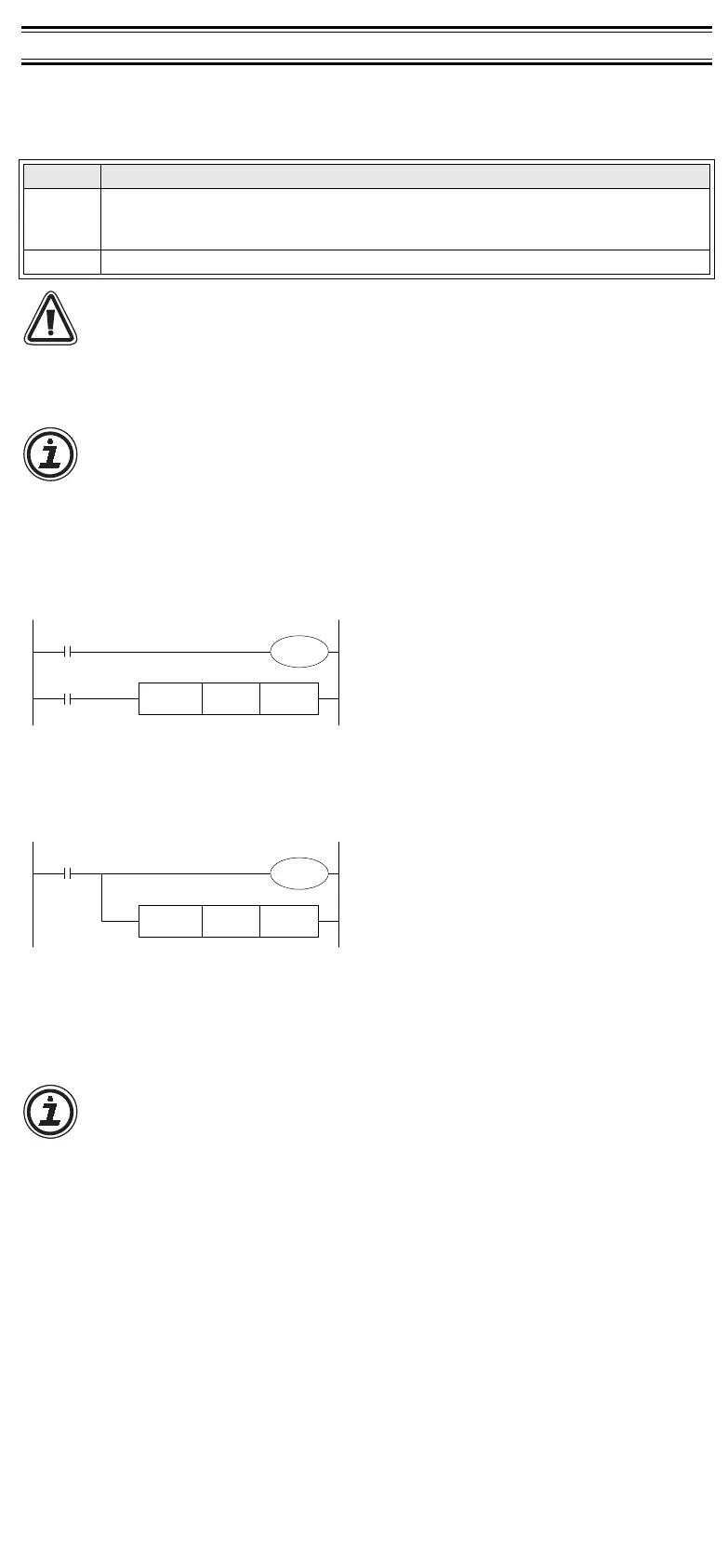
Drive M8114 which specifies the digital to analog conversion characteristic with M8000 (“a”
type contact of the RUN monitor) or M8001 (“b” type contact of the RUN monitor).
Do not change the ON/OFF state while the digital to analog conversion is operating.
The Digital to analog conversion is not executed correctly when M8114 is turned ON and OFF
during the conversion process.
5.2.1 Voltage Output Mode
The following program example sets the voltage output mode, and a digital value in D0 is converted to
analog.
*1 If a digital value is not stored in D0, D8114 can be used directly for other instructions.
5.2.2 Current Output Mode
The following program example sets the current output mode, and a digital value in D2 is converted to
analog.
*1 If a digital value is not stored in D2, D8114 can be used directly for other instructions.
5.3 Example Application Program
As the 1DA does not have Offset and Gain capabilities, if values are required outside the standard
specification range, additional program commands are required to either multiply or divide the conversion
values. For an example application program, please see FX programming manual II.
Note:
• Accuracy and resolution of the digital to analog conversion are different from the
specification because of the additional program commands.
• The original range of the analog output is not changed.
Table 5.1: Allocation of Device
Device Description
M8114
Switch of output mode
OFF: Voltage output mode (0 ~ 10V)
ON: Current output mode (4 ~ 20mA)
D8114 Digital value (When power supply is turned ON, D8114 will initials to “0”.)
Set in voltage output mode (0 ~ 10V).
D0
*1
is converted digital value to analog output.
M8001
M8000
M8114
FNC 12
MOV
D8114D0
*1
Set in current output mode (4 ~ 20mA).
D2
*1
is converted digital value to analog output.
M8000
M8114
FNC 12
MOV
D8114D2
*1
5.3.1 Example Application Program 1
In voltage output mode, the 1DA converts digital values from 0 ~ 4000 to the analog output of 0 ~ 10 Volts.
If using a digital range of 0 ~ 10000 in the program, the range must be converted to 0 ~ 4000 as shown in
the programming example below. Digital values for conversion to analog are stored in D8114.
The analog output does not have exact resolution of 2.5mV because the digital value is converted from 0
~ 10000 to a range of 0 ~ 4000.
If a digital value in the range of 0 ~ 10000 is used in D0, please see below.
Digital value used in user program: (D8114) = 2
×
D0
÷
5
The value of D0 is given as a multiple of five.
5.3.2 Example Application Program 2
In current output mode, the 1DA converts digital values from 0 ~ 2000 to the analog output of 0 ~ 20 mA.
If using a digital range of 0 ~ A in the program, the range must be converted to 0 ~ 4000 as shown in the
programming example below. Digital values for conversion to analog are stored in D8114.
The analog output does not have exact resolution of 8
µ
A because the digital value is converted from 0 ~
A to range of 0 ~ 2000. A > 0.
If a digital value in the range of 0 ~ A is used in D60, please see below.
Digital value used in user program: D8114 = 2000
×
D60
÷
A
= 2000
×
D60
÷
10000 (In A = 10000 case)
= D60
÷
5
The value of D60 is given as a multiple of five
0
0
4000
10000
Digital value for
analog output
(D8114)
Analog
output
Digital value used in user program (D0)
0
0
10V
4000
Digital value for analog output (D8114)
M8001
M8000
M8114
FNC 22
MUL
K2 D0
FNC 23
DIV
D2 K5
D2
D4
D
FNC 12
MOV
D4 D8114
0
0
2000
A
Digital value for
analog output
(D8114)
Analog
output
Digital value used in user program (D60)
0
0
20mA
2000
Digital value for analog output (D8114)
4mA
M8000
M8114
FNC 23
DIV
D60 K5 D62
FNC 12
MOV
D62 D8114
Manual number : JY992D96401
Manual revision: B
Date : JULY 2004

 Loading...


