3. Power supply/input/output specifications
and examples of external wiring
As for the details of the power supply wiring and input/output wiring,
refer to FX3U Series User's Manual - Hardware Edition.
3.1 Wiring
3.1.1 Cable end treatment and tightening torque
For the terminals of FX3U series PLC, M3 screws are used.
The electric wire ends should be treated as shown below.
Tighten the screws to a torque of 0.5 N
•
m to 0.8 N
•
m.
• When one wire is connected to one terminal
• When two wires are connected to one terminal
3.1.2 Removal and installation of quick-release terminal
block
Removal Unscrew the terminal block mounting screw [both right
and left screws] evenly, and remove the terminal block.
Installation Place the terminal block in the specified position, and
tighten the terminal block mounting screw evenly [both
right and left screws].
Tightening torque 0.4 to 0.5 N
•
m
* Pay attention so that the center of the terminal block
is not lifted.
DESIGN
PRECAUTIONS
• Make sure to have the following safety circuits outside of the
PLC to ensure safe system operation even during external
power supply problems or PLC failure.
Otherwise, malfunctions may cause serious accidents.
1) Most importantly, have the following: an emergency stop
circuit, a protection circuit, an interlock circuit for opposite
movements (such as normal vs. reverse rotation), and an
interlock circuit (to prevent damage to the equipment at the
upper and lower positioning limits).
2) Note that when the PLC CPU detects an error, such as a
watchdog timer error, during self-diagnosis, all outputs are
turned off. Also, when an error that cannot be detected by
the PLC CPU occurs in an input/output control block,
output control may be disabled.
External circuits and mechanisms should be designed to
ensure safe machinery operation in such a case.
3) Note that when an error occurs in a relay, triac or transistor
output device, the output could be held either on or off.
For output signals that may lead to serious accidents,
external circuits and mechanisms should be designed to
ensure safe machinery operation in such a case.
DESIGN
PRECAUTIONS
• Do not bundle the control line together with or lay it close to the
main circuit or power line. As a guideline, lay the control line at
least 100mm (3.94") or more away from the main circuit or
power line.
Noise may cause malfunctions.
• Install module so that excessive force will not be applied to the
built-in programming connectors, power connectors or I/O
connectors.
Failure to do so may result in wire damage/breakage or PLC
failure.
Notes
• Simultaneously turn on and off the power supplies of the main
unit and extension devices.
• Even if the power supply causes an instantaneous power failure
for less than 10 ms, the PLC can continue to operate.
• If a long-time power failure or an abnormal voltage drop occurs,
the PLC stops, and output is turned off. When the power
supply is restored, it will automatically restart (when the RUN
input is on).
WIRING
PRECAUTIONS
• Cut off all phases of the power supply externally before
installation or wiring work in order to avoid damage to the
product or electric shock.
WIRING
PRECAUTIONS
• Connect the AC power supply to the dedicated terminals
specified in this manual.
If an AC power supply is connected to a DC input/output
terminal or DC power supply terminal, the PLC will burn out.
• Do not wire vacant terminals externally.
Doing so may damage the product.
• Use class D grounding (grounding resistance of 100Ω or less)
with a wire of 2mm
2
or thicker on the grounding terminal of the
FX3U Series main unit.
However, do not connect the ground terminal at the same point
as a heavy electrical system.
• When drilling screw holes or wiring, make sure cutting or wire
debris does not enter the ventilation slits.
Failure to do so may cause fire, equipment failures or
malfunctions.
Notes
• Input/output wiring 50 to 100 m (164’1” to 328’1”) long will
cause almost no problems of noise, but, generally, the wiring
length should be less than 20 m (65’7”) to ensure the safety.
• Extension cables are easily affected by noise. Lay the cables
at a distance of at least 30 to 50 mm (1.19” to 1.97”) away from
the PLC output and other power lines.
φ
3.2 (0.13")
6.2 mm (0.24")
or less
’[Žq
Terminal
screw
Solderless
terminal
Terminal
6.2 mm (0.24")
or less
φ
3.2 (0.13")
6.3 mm(0.25")
or more
6.3 mm(0.25")
or more
Terminal
screw
Solderless
terminal
Terminal
6.2 mm (0.24")
or less
6.2 mm (0.24")
or less
φ
3.2 (0.13")
φ
3.2 (0.13")
3.2 Power supply specifications and example of
external wiring
→ Refer to FX3U Series User's Manual - Hardware Edition.
3.2.1 Power supply specifications
The specifications for the power supply of the main unit are
shown in the following table.
*1 Does not include the power consumption of extension units /
special extension units, and of the extension blocks / special
extension blocks connected to those units.
For the power (current) consumed by the extension units/
blocks for input/output, refer to FX3U Series User's Manual -
Hardware Edition.
For the power consumed by the special extension units/blocks,
refer to the appropriate manual.
*2 When input/output extension blocks are connected, the 24V
DC service power supply is consumed by the blocks, and the
current value to be used by the main unit is reduced.
*3 Cannot be used to supply power to an external destination.
The power is supplied to input/output extension blocks, special
extension blocks, special adapters and expansion boards.
*4 When the supply voltage is 200 V AC, the time can be changed
to 10 to 100 ms by editing the user program.
*5 FX3U-128M does not have DC power supply.
*6 When supply voltage is DC 16.8-19.2V, the connectable
extension equipment decreases. The following manual shows
further information.
→ Refer to FX3U Series User’s Manual - Hardware Edition.
*7 When attaching high-speed input/output special adapter
(FX3U-4HSX-ADP, FX3U-2HSY-ADP) and special function
block (FX0N-3A, FX2N-2AD, FX2N-2DA), the number of
connectable modules to the main unit is limited, due to the
current consumption (internal 24V DC) at startup. The following
manual shows further information.
→ Refer to FX3U Series User’s Manual - Hardware Edition.
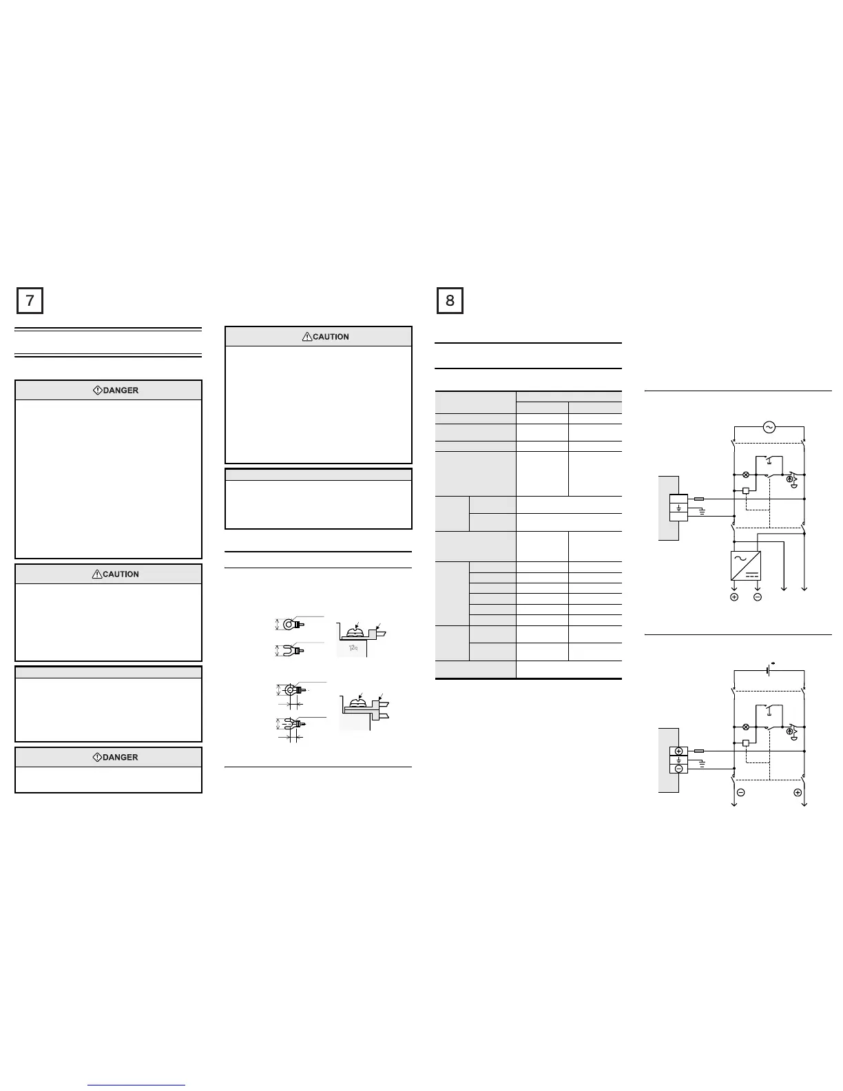
3.2.2 Example of external wiring (AC power type)
100 to 240V AC power is supplied to the main unit. For the details of
wiring work, refer to section 3.1.
3.2.3 Example of external wiring (DC power type)
24V DC power is supplied to the main unit. For the details of wiring
work, refer to section 3.1.
Item
Specification
AC power type
DC power type
*7
Supply voltage 100 - 240V AC 24 V DC
Allowable
supply voltage
range
85 - 264V AC
16.8-28.8V DC
*6
Rated frequency 50/60Hz −
Allowable instantaneous
power failure time
Operation can be
continued upon
occurrence of
instantaneous
power failure for
10 ms or less.
*4
Operation can be
continued upon
occurrence of
instantaneous
power failure for 5
ms or less.
Power
fuse
FX3U-16M to
32M
250V AC 3.15A
FX3U-48M to
128M
*5
250V AC 5A
Rush current
30 A max. 5 ms or
less/100 V AC
65 A max. 5 ms or
less/200 V AC
35 A max. 0.5 ms
or less/24 V DC
Power
consumption
*1
FX3U-16M 30W 25W
FX3U-32M 35W 30W
FX3U-48M 40W 35W
FX3U-64M 45W 40W
FX3U-80M 50W 45W
FX3U-128M
*5
65W −
24V DC
service
power
supply
*2
FX3U-16M to
32M
400 mA or less −
FX3U-48M to
128M
*5
600 mA or less −
5V DC built-in power
supply
*3
500 mA or less
100 to 240V AC
PL
Power on
Emer-
gency
stop
MC
MC
DC
power
supply
Power supply for loads connected
to PLC output terminals
DC AC
MCMC
*
Fuse
L
N
PLC
*Class D grounding
Refer to section 3.3
for details.
Breaker
24V DC
PL
Power on
Emer-
gency
stop
MC
MC
Power supply for loads connected
to PLC output terminals
MCMC
*
Fuse
PLC
*Class D grounding
Refer to section 3.3
for details.
Circuit protector

 Loading...


