2. Installation (general specifications)
As for installation of the input/output extension blocks, special
adapters and expansion boards, refer to FX3U Series User's Manual
- Hardware Edition.
2.1 Generic specifications [Main unit]
*1
For dielectric with stand voltage test and insulation
resistance test of each product, refer to the following manual.
→ Refer to FX3U Series User's Manual - Hardware Edition.
*2 For common grounding, refer to section 3.3.
*3 The PLC cannot be used at a pressure higher than the
atmospheric pressure to avoid damage.
2.2 Installation location
Install the PLC in an environment conforming to the generic
specifications (section 2.1), installation precautions and notes.
INSTALLATION
PRECAUTIONS
•
Use the product within the generic environment specifications
described in section 2.1 of this manual.
Never use the product in areas with excessive dust, oily smoke,
conductive dusts, corrosive gas (salt air, Cl
2
, H
2
S, SO
2
or NO
2
),
flammable gas, vibration or impacts, or exposed to high
temperature, condensation, or rain and wind.
If the product is used in such conditions, electric shock, fire,
malfunctions, deterioration or damage may occur.
•
Do not touch the conductive parts of the product directly to avoid
failure or malfunctions.
•
Install the product securely using a DIN rail or mounting screws.
• Install the product on a flat surface.
If the mounting surface is rough, undue force will be applied to
the PC board, thereby causing nonconformities.
• When drilling screw holes or wiring, make sure cutting or wire
debris does not enter the ventilation slits.
Failure to do so may cause fire, equipment failures or
malfunctions.
• Be sure to remove the dust proof sheet from the PLC's
ventilation port when installation work is completed. Failure to
do so may cause fire, equipment failures or malfunctions.
• Connect the extension cables, peripheral device cables, input/
output cables and battery connecting cable securely to their
designated connectors.
Unsecured connection may cause malfunctions.
• Turn off the power before attaching or detaching the following
devices.
Failure to do so may cause device failures or malfunctions.
- Peripheral devices, display modules, expansion boards and
special adapters
- Extension units/blocks and the FX Series terminal block
- Battery and memory cassette
Notes
• When a dust proof sheet is supplied with an extension unit/
block, keep the sheet applied to the ventilation slits during
installation and wiring work.
• To prevent temperature rise, do not install the PLC on a floor, a
ceiling or a vertical surface.
Install it horizontally on a wall as shown in section 2.2.
• Keep a space of 50 mm (1.97”) or more between the unit main
body and another device or structure (part A). Install the unit as
far away as possible from high-voltage lines, high-voltage
devices and power equipment.
WIRING
PRECAUTIONS
• Cut off all phases of the power supply externally before
installation or wiring work in order to avoid damage to the
product or electric shock.
Item Specification
Ambient
temperature
0 to 55°C (32 to 131°F) when operating and -25 to
75°C (-13 to 167°F) when stored
Ambient
humidity
5 to 95%RH (no condensation) when operating
Vibration
resistance
Fre-
quency
(Hz)
Accele-
ration
(m/s
2
)
Half
amplitude
(mm)
Sweep Count
for X, Y, Z: 10
times
(80 min in
each direction)
When
installed
on DIN
rail
10 to 57 - 0.035
57 to 150
4.9 -
When
installed
directly
10 to 57 - 0.075
57 to 150
9.8 -
Shock
resistance
147 m/s
2
Acceleration, Action time: 11ms, 3 times by
half-sine pulse in each direction X, Y, and Z
Noise
resistance
By noise simulator at noise voltage of 1,000 Vp-p,
noise width of 1 µs, rise time of 1 ns and period of 30
to 100 Hz
Dielectric
withstand
voltage
*1
1.5kV AC for one
minute
Between each terminals
*1
and
ground terminal
500V AC for one
minute
Insulation
resistance
*1
5MΩ or more by
500V DC megger
Grounding
Class D grounding (grounding resistance: 100 Ω or
less) <Common grounding with a heavy electrical
system is not allowed.>
*2
Working
atmosphere
Free from corrosive or flammable gas and excessive
conductive dusts
Working
altitude
<2000m
*3
Terminal
Dielectric
strength
Insulation
resistance
Between power supply
terminal (AC power) and
ground terminal
1.5 kV AC for
one minute
5MΩ or more by
500V DC megger
Between power supply
terminal (DC power) and
ground terminal
500V AC for
one minute
Between input terminal
(24V DC) and ground
terminal
500V AC for
one minute
Between output terminal
(relay) and ground
terminal
1.5 kV AC for
one minute
Between output terminal
(transistor) and ground
terminal
500V AC for
one minute
Item Specification
For more details, refer to FX
3U
Series User's Manual - Hardware
Edition.
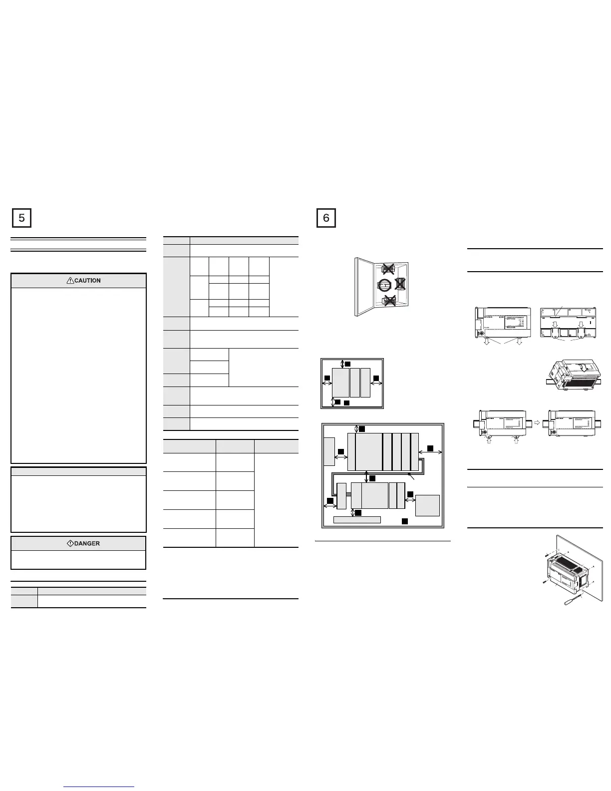
Installation location in enclosure
Space in enclosure
Extension devices can be connected on the left and right sides of the
main unit of the PLC.
If you intend to add extension devices in the future, keep necessary
spaces on the left and right sides.
2.2.1 Affixing The Dust Proof Sheet
The dust proof sheet should be affixed to the ventilation port before
beginning the installation and wiring work.
→ For the affixing procedure, refer to the instructions on the
dust proof sheet.
Be sure to remove the dust proof sheet when the installation and
wiring work is completed.
2.3 Procedures for installing to and detaching from
DIN rail
The main unit can be installed on a DIN46277 rail [35 mm (1.38”)
wide].
2.3.1 Installation
1) Connect the expansion boards and special adapters to the main
unit.
2) Push out all DIN rail mounting hooks (below fig.A)
3) Fit the upper edge of the DIN rail
mounting groove (right fig.C)
onto the DIN rail.
4) Lock the DIN rail mounting hooks (below fig.D) while pressing the
PLC against the DIN rail.
2.4 Procedures for installing directly (with M4
screws)
The product can be installed directly on the panel (with screws).
2.4.1 Mounting hole pitches
Refer to the External Dimensions (section 1.2) for the product's
mounting hole pitch information.
As for the details of the mounting hole pitches for extension unit/
block and special adapters, refer to the following manual.
→ Refer to FX3U Series User's Manual - Hardware Edition.
2.4.2 Installation
1) Make mounting holes in the
mounting surface referring to
the external dimensions
diagram.
2) Fit the main unit (A in the right
figure) based on the holes, and
secure it with M4 screws (B in
the right figure).
The mounting hole pitches and
number of screws depend on
the product. Refer to the
external dimensions diagram.
FX
3U
-48MFX
3U
-48M
≥
50mm (1.97")
A
A
A
A
A
FX
3U
Series
main
unit
FX
2N
-16EX
-ES/UL
FX
2N
-16EYT
-ESS/UL
Configuration without extension cable
Another equipment
Another
equipment
Extension
cable
·FX
0N
-65EC
·FX
0N
-30EC
Another
equipment
A
A
A
A
A
A
A
A
≥
50mm (1.97")
Configuration in 2 stages with extension cable
FX
2N
-CNV-BC
Input/output
powered
extension
unit
FX
2N
-16EX
-ES/UL
FX
2N
-10PG
FX
2N
-8AD
FX
3U
Series
main unit
FX
2N
-16EX-ES/UL
FX
2N
-16EYT-ESS/UL
FX
2N
-4AD
FX
2N
-16EYR-ES/UL
FX
3U
-4AD-ADP
A
2)2)
2)
A
2)
C
C
RUN
STOP
FX

 Loading...


