5
4. Connecting the MA & CONTACT Terminal Interface with each system
(For details on each system, see the relevant instruction manual.)
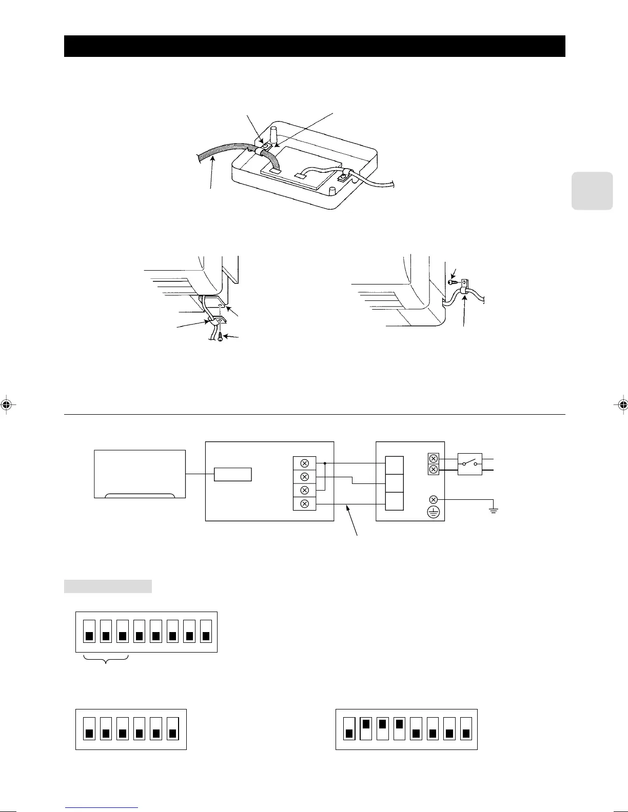
• Replace the interface unit 1 mounting cord clamp with a supplied mounting cord clamp 5–7 based on the thickness of the
connecting cable used for each system.
Interface unit 1 mounting cord clamp or mounting
cord clamps 5–7
Mounting screws 8 3.5 × 12
Connecting cable for each system
Mounting cord clamp 6
Mounting cord clamp 6
Electrical wire mounting
bracket
Mounting screws 0 4 × 16
Mounting screws 9 4 × 10
• The cables connected to the Indoor Unit should be mounted on or near the Indoor Unit.
If the connecting cable is not securely mounted, the connector may detach, break, or malfunction.
• Set the interface dip switch (SW500–502) settings before turning on the power.
• If the interface dip switch (SW500–502) settings are not set correctly, the system will not function properly.
4.1. Centralized Control (When Connecting to a Centralized on-off remote Controller)
Power supply
~/N 220-240 V
50/60 Hz
CN560
TB571
D
C
M
TC1
TC2
TM1
TM2
Indoor unit
Interface unit 1
* Centralized on-off
remote controller C
*Breaker B
Ground
Dip switch settings
■ SW500
■ SW501 and SW502 do not have to be set.
ON
1
2 3 4 5 6 7 8
* Refer to the installation manual of centralized on-off remote controller.
ON
1
2 3 4 5 6
SW501
SW502
Setting required
Extend the cord using the extension
cord A at the installation site.
ON
1
2 3 4 5 6 7 8
 Loading...