2 - 31 2 - 31
MELSEC-Q
2 INPUT MODULE SPECIFICATIONS
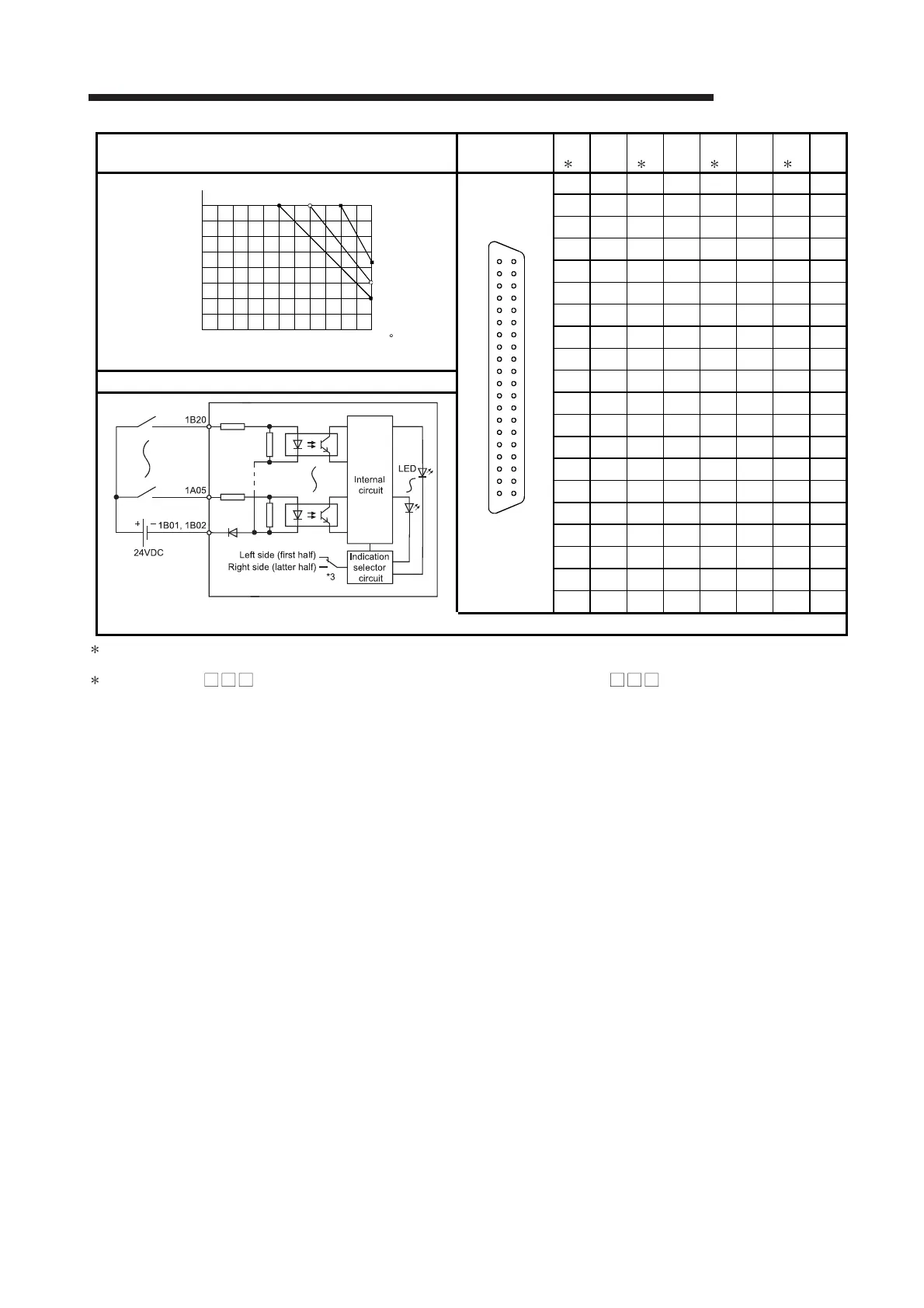
Derating chart Pin-Outs
Pin
No.
4
Signal
No.
Pin
No.
4
Signal
No.
Pin
No.
4
Signal
No.
Pin
No.
4
Signal
No.
Module front
view
1B20 X00 1A20 X10 2B20 X20 2A20 X30
1B19 X01 1A19 X11 2B19 X21 2A19 X31
1B18 X02 1A18 X12 2B18 X22 2A18 X32
1B17 X03 1A17 X13 2B17 X23 2A17 X33
1B16 X04 1A16 X14 2B16 X24 2A16 X34
1B15 X05 1A15 X15 2B15 X25 2A15 X35
1B14 X06 1A14 X16 2B14 X26 2A14 X36
1B13 X07 1A13 X17 2B13 X27 2A13 X37
1B12 X08 1A12 X18 2B12 X28 2A12 X38
External connection
1B11 X09 1A11 X19 2B11 X29 2A11 X39
The above diagram shows the first half of 32 points (F).
The latter half of 32 points (L) are similar.
1B10 X0A 1A10 X1A 2B10 X2A 2A10 X3A
1B09 X0B 1A09 X1B 2B09 X2B 2A09 X3B
1B08 X0C 1A08 X1C 2B08 X2C 2A08 X3C
1B07 X0D 1A07 X1D 2B07 X2D 2A07 X3D
1B06 X0E 1A06 X1E 2B06 X2E 2A06 X3E
1B05 X0F 1A05 X1F 2B05 X2F 2A05 X3F
1B04 Vacant 1A04 Vacant 2B04 Vacant 2A04 Vacant
1B03 Vacant 1A03 Vacant 2B03 Vacant 2A03 Vacant
1B02 COM1 1A02 Vacant 2B02 COM2 2A02 Vacant
1B01 COM1 1A01 Vacant 2B01 COM2 2A01 Vacant
3:
Selection
of left-hand (F) side provides the first half (X00 to X1F) LED indications, and selection of right-hand (L) side provides the
latter half (X20 to X3F) LED indications.
4: Pin number of 1 indicates that of the left-hand side connector, and pin number of 2 indicates that of the right-hand
side connector.
100
90
80
70
60
50
40
0102030405055
Ambient temperature
24VDC
30
20
26.4VDC
28.8VDC
( )
(%)
C
ON ratio/
common
A20
A19
A18
A17
A16
A15
A14
A13
A12
A11
A10
A9
A8
A7
A6
A5
A4
A3
A2
A1
B20
B19
B18
B17
B16
B15
B14
B13
B12
B11
B10
B9
B8
B7
B6
B5
B4
B3
B2
B1
 Loading...