-
152
-
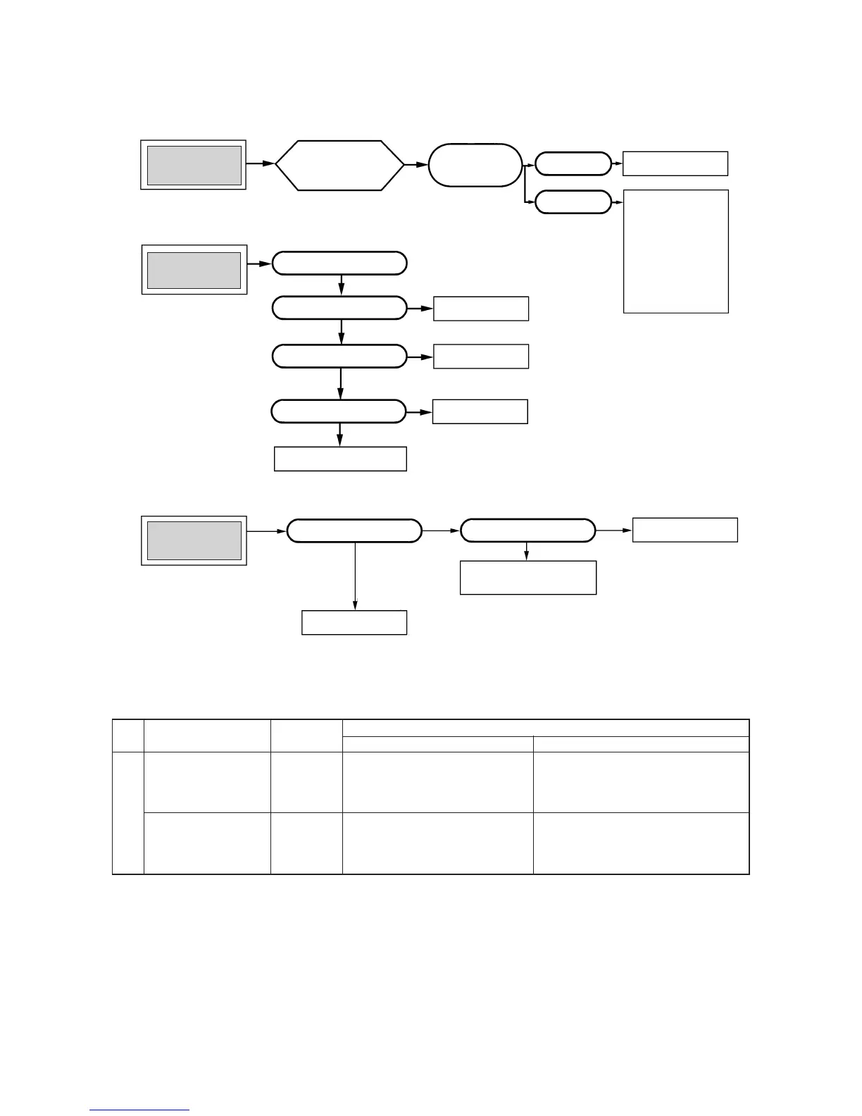
(d) Trouble Diagnostic Procedures
Unit malfunctions or
does not stop.
Replace PCB.
Microcomputer rarely
mis-starts even during
times or power supply
or power failure, but, it
can sometimes occur
during those times. If it
occurs, check the opera-
tion, when the result is
positive then proceed as
normal.
Runaway of micro-
computer
Remove receptacle.
Insert it after 3 min.
and operate.
No change.
Normal operation.
Indoor light of
indoor unit does not
illuminate.
Check receptacle voltage.
Check if PCB fuse is blown.
Check varistor.
Check transformer secondary
voltage
Replace PCB.
Replace fuse.
Replace varistor.
Replace transformer
No
No
Outdoor fan does not
operate.
Check voltage with fan
connector.
Replace PCB.
Check capacitor.
Replace fan motor.
Replace capacitor.
Abnormal
Yes
Normal
Unit sensor Operation
Function
Short circuit Broken connection
Cooling
Cooling
Indoor unit
Room temperature
sensor
(1)
(Th1) except for
“continuous” thermal
setting.
Cooling will not operate
¡ FM
I : continuous operation
¡ CM,FM
o: stopped
Cooling will operate
¡ Heat exchanger frost preventer begins to operate
¡ Cools alternately for 10 minutes, stopping for 3
minutes.
(e) Trouble shooting chart for the room temperature sensor (Th1), heat exchanger sensor (Th2)
Continuous Cooling operation
¡ Cannot be turned ON/OFF by thermostat
¡ When FMI is on. “AUTO” is continuously
Hi
Heat exchanger
sensor (Th
2)
Cooling will not operate.
Note (1) When the room temperature sensor (Th
1) will not operate normally. Cooling operation may be run continuously by putting the thermostat setting on “CONTINUOUS”
 Loading...