September 26, 2003 6881096C77-O
5-8 Troubleshooting: Replacing the Control-Head Board
11. Remove the circuit-board assembly from the housing.
12. Remove the keypad [6] from the housing assembly [7].
5.6.2 W4, W5, and W7 Control Heads
NOTE: For the following procedure, refer to Chapter 7: Exploded Views and Parts Lists, beginning
on
page 7-1, for the exploded view and associated parts list applicable to the model being
disassembled.
1. Unplug the microphone.
2. Remove the two front-panel screws using a 2.5 mm hex-key driver.
3. Disconnect the control cable on remote models.
4. Grasp the front panel firmly, and carefully unplug the control-head assembly from the radio or
remote control-head back housing.
5. Lay the control head face down on a clean, flat surface, being careful not to scratch or mar
the display.
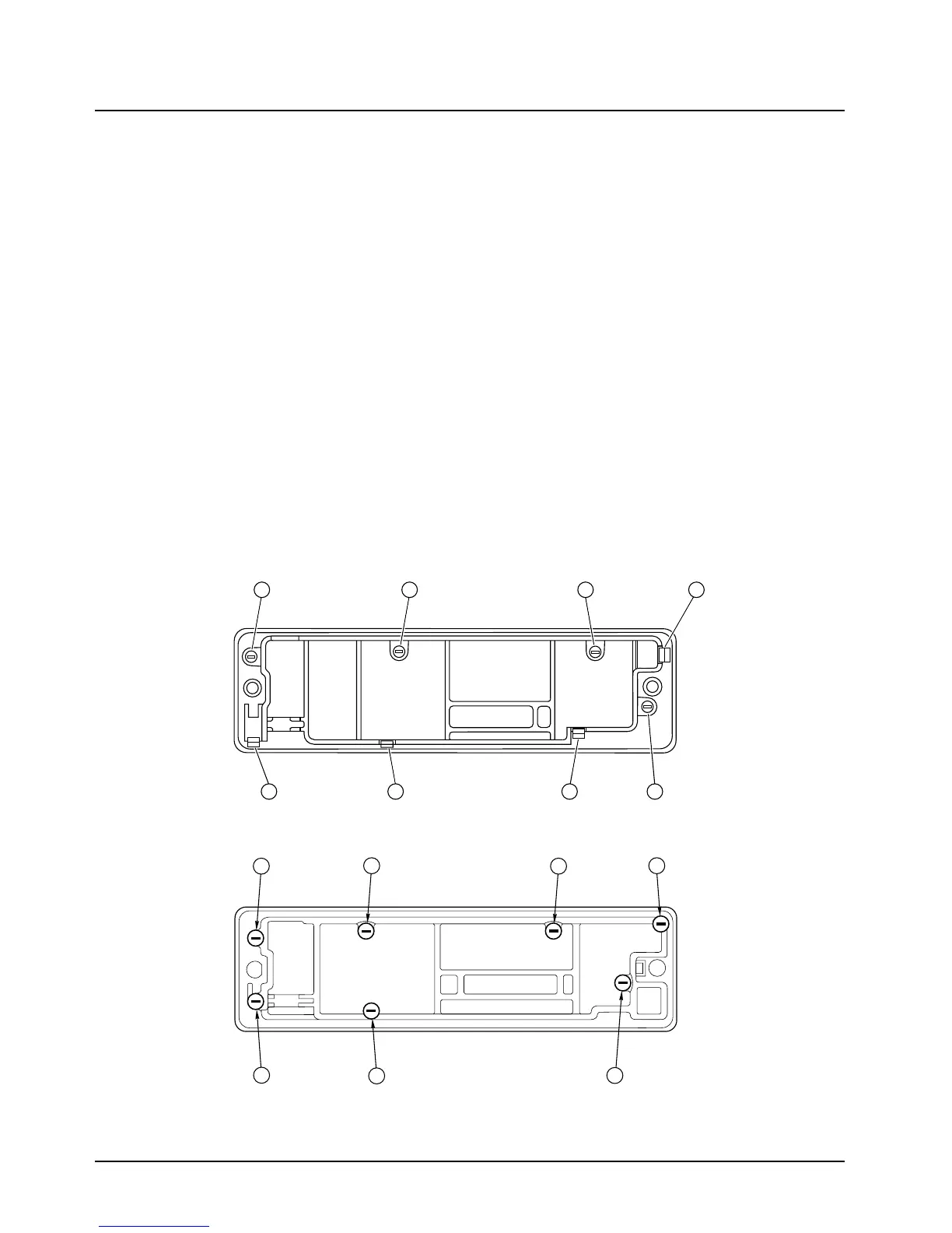
6. Using a Torx T10 driver, remove the control-head screws:
- W4 Control Head: four screws [callouts 5-8], as shown in
Figure 5-2.
The W4 control head has, in addition to the screws, four snap features [callouts 1-4], which
are shown in
Figure 5-2.
- W5 and W7 Control Heads: seven screws, as shown in
Figure 5-3.
Figure 5-2. Model W4 Rotary Control Head Assembly Screw and Snap Sequence
Figure 5-3. Models W5 and W7 Pushbutton Control Head Assembly Screw Sequence
7 1
58
3
4
2 6
416
2
5
3
7
 Loading...


