Chapter 2
THEORY OF OPERATION
1.0 Introduction
This Chapter provides a detailed theory of operation for the UHF circuits in the radio. For details of
the theory of operation and trouble shooting for the the associated Controller circuits refer to the
Controller Section of this manual.
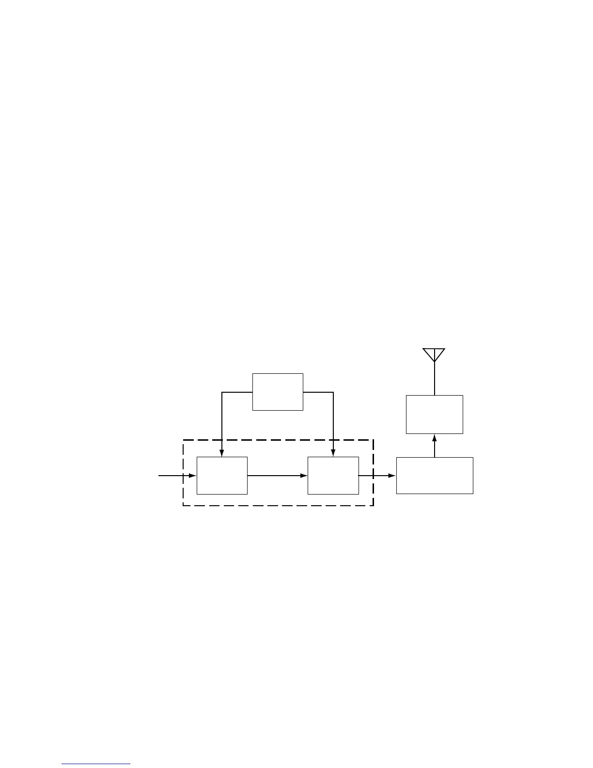
2.0 800 MHz Transmitter
(
Refer to Figure 2-1 and the 800 MHz Transmitter schematic diagram
)
The 800 MHz transmitter consists of the following basic circuits:
1. Power amplifier (PA).
2. Antenna switch.
3. Harmonic filter.
4. Power Control Integrated Circuit (PCIC).
Figure 2-1 800 MHz Transmitter Block Diagram.
2.1 Power Amplifier
The power amplifier (PA) consists of two principle devices:
1. 63J66 driver IC (U101).
2. 85Y73 LDMOS PA (Q101).
The 63J66 driver IC contains a 2 stage amplification with a supply voltage of 7.5V.
PCIC
PA
Driver
Antenna Switch/
Harmonic Filter
PA Final
Stage
Vcontrol
Vcontrol
Antenna
Jack
From VCO
Power Amplifier (PA)
 Loading...