1-2 THEORY OF OPERATION
3.0 Controller Circuits
3.1 Controller Architecture
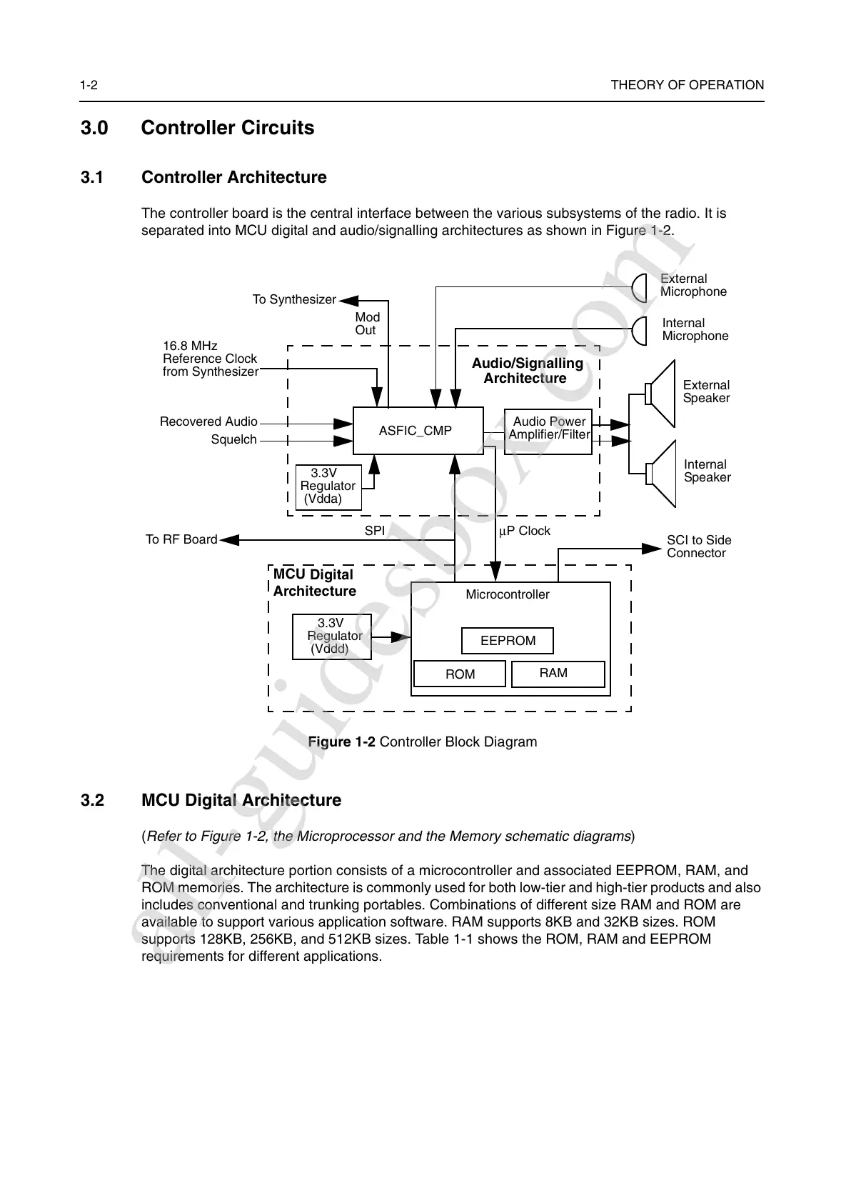
The controller board is the central interface between the various subsystems of the radio. It is
separated into MCU digital and audio/signalling architectures as shown in Figure 1-2.
Figure 1-2 Controller Block Diagram
3.2 MCU Digital Architecture
(
Refer to Figure 1-2, the Microprocessor and the Memory schematic diagrams
)
The digital architecture portion consists of a microcontroller and associated EEPROM, RAM, and
ROM memories. The architecture is commonly used for both low-tier and high-tier products and also
includes conventional and trunking portables. Combinations of different size RAM and ROM are
available to support various application software. RAM supports 8KB and 32KB sizes. ROM
supports 128KB, 256KB, and 512KB sizes. Table 1-1 shows the ROM, RAM and EEPROM
requirements for different applications.
External
Microphone
Internal
Microphone
External
Speaker
Internal
Speaker
SCI to Side
Connector
Audio/Signalling
Architecture
To Synthesizer
Mod
Out
16.8 MHz
Reference Clock
from Synthesizer
Recovered Audio
Squelch
To RF Board
SPI
MCU
Digital
µP Clock
3.3V
Regulator
(Vddd)
RAM
EEPROM
ROM
Microcontroller
ASFIC_CMP
3.3V
Regulator
(Vdda)
Architecture
Audio Power
Amplifier/Filter
All manuals and user guides at all-guidesbox.com
all-guidesbox.com
 Loading...